









DMX Fixture On-Site Commissioning: 10 Common Faults and Troubleshooting Protocols
A field-first isolation guide for power, RS-485 / DMX signal, addressing, network discovery, long-run integrity and stand-alone playback faults.
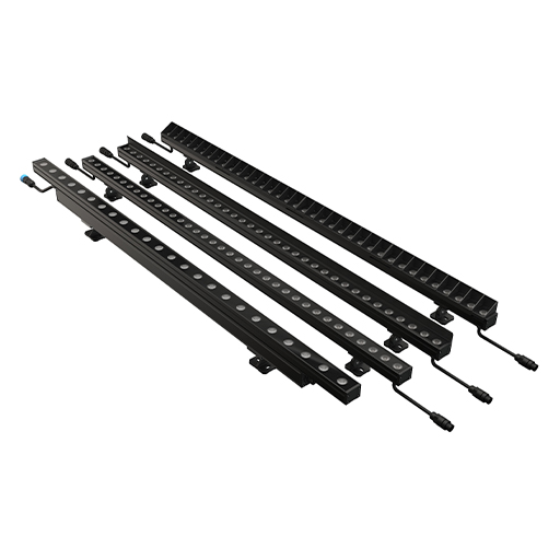
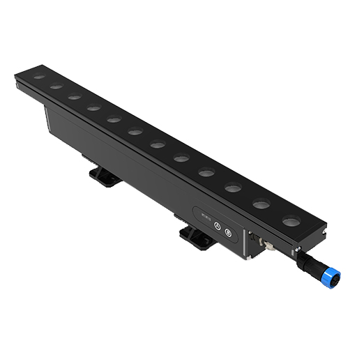
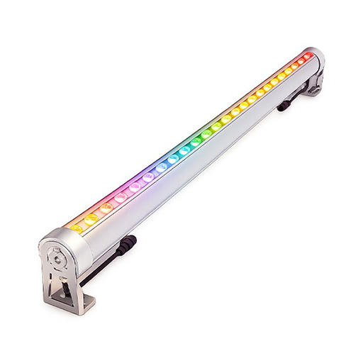
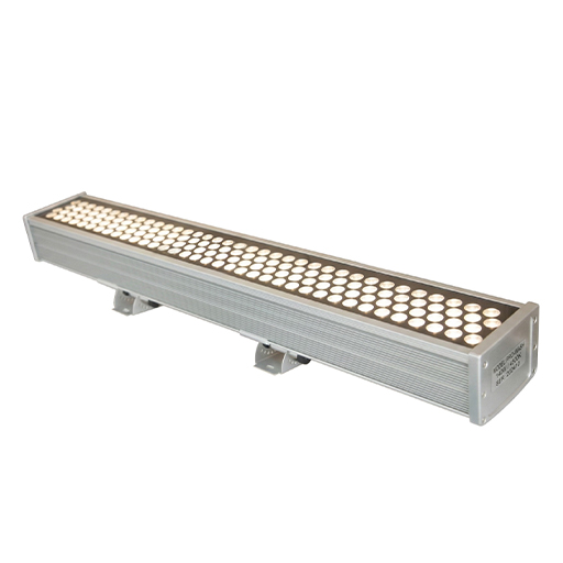
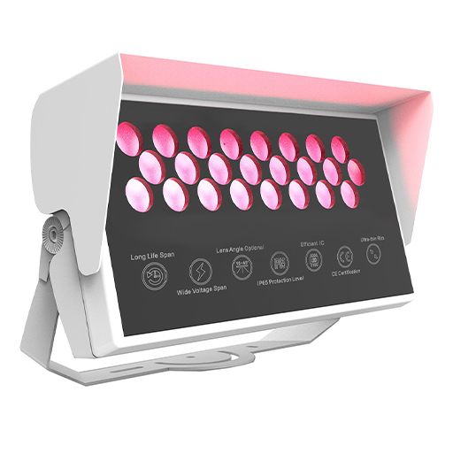
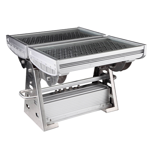
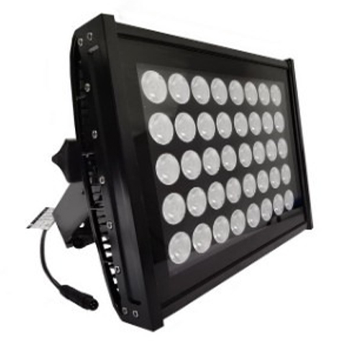
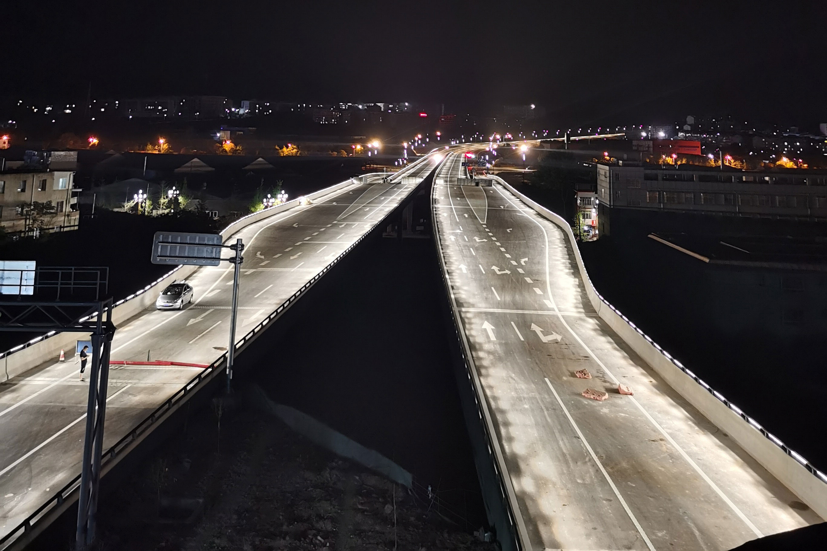
Much of this guide comes directly from a real long-span river crossing — our Fujiang River Bridge project — where the control layer ran on DMX512 RGBW LWW-PZT-W38 wall washers over cable runs of several hundred metres. The same long-run faults described below showed up during on-site commissioning, so we documented the isolation sequence we actually used in the field.
Field faults trace to six root causes
- Master and sub-controller configurations
- RS-485 / DMX signal transmission paths
- DMX addressing, patch tables, and physical port assignments
- Low-voltage DC distribution and line voltage drop
- Ingress protection failures, moisture intrusion, and site conditions
- Show files, scene programming, and stand-alone playback files
1. Fixture Flickering or Intermittent Control
Do not assume driver IC or emitter failure when flickering occurs.
Key checkpoints
- Polarity and Terminations: Inverted Data+ (A) and Data- (B) lines, cold solder joints, loose terminals, or a floating shield wire inducing ground-loop interference.
- Line Voltage Drop: DC voltage at the end of the run dropping below the driver IC operating threshold, triggering continuous driver reset loops.
- Operation Mode: Fixtures stuck in factory auto-cycle/test modes conflicting with external DMX data.
- Inline Hardware: Overheated, defective, or underpowered DMX splitters and repeaters.
2. Color Sequence Mismatches (RGBW Channel Order)
Software outputs Red, but the physical fixture displays White, Green, or Blue.
Key checkpoints
- Fixture optical channel order (e.g., RGBW, GRBW, BRGW) mismatched against the controller patch profile.
- Incorrect channel footprint (e.g., a 3-channel profile assigned to a 4-channel fixture).
- Inverted wiring between external DMX decoders and fixture leads.
3. Multiple Fixtures Responding Simultaneously (Address Overlap)
Two or more fixtures mirror each other during chase sequences, or a single-pixel chase stalls.
Key checkpoints
- Duplicate DMX start addresses assigned to multiple fixtures.
- Calculation errors in address intervals: A 4-channel RGBW fixture starting at address 001 requires the next unit to start at 005, followed by 009. An offset error creates overlapping control.
4. Chase Sequences Inverting or Skipping Physical Locations
The software shows a left-to-right sweep, but the facade illuminates out of order or reverses direction.
Key checkpoints
- Discrepancies between field installation sequence and engineering shop drawings.
- Field rerouting around architectural obstacles, or inverted main trunk feeder runs.
- Output test data to a single physical port (e.g., Port 1).
- Record the physical location, orientation, and fixture range illuminated.
- Repeat across all output ports.
- Remap the software patch table to match field reality. Do not re-pull field cabling to match outdated drawings.
5. Complete Branch or Zone Failure (Blackout)
When an entire branch stays dark, differentiate power loss from signal interruption.
Key checkpoints
- Sub-controller port status LEDs and packet transmission.
- Power supply DC rail output and power injection lines (T-taps).
- Line short between Data- (B) and GND, which pulls down the RS-485 differential bus.
- Crushed cables, pulled conductors, or severed cores.
6. Controller or Node Discovery Failure in Software
Management software fails to detect Art-Net/sACN nodes or sub-controllers.
Key checkpoints
- Host PC network adapter IP configuration versus sub-controller subnet masks and gateways.
- Network switch power, port link LEDs, and T568B RJ45 crimp continuity.
- Software network interface binding (e.g., software bound to a wireless adapter instead of the physical Ethernet NIC).
- Controller power supply and RUN/ACT status LED heartbeat cycles.
7. Signal Degradation and Packet Loss over Long Cable Runs
Fixtures pass bench testing but exhibit jitter, latency, or packet loss once deployed on extended architectural runs.
Key checkpoints
- Cable runs exceeding RS-485 operational limits (controller to first fixture, or inter-fixture spans).
- Non-shielded cable runs routed parallel to high-voltage AC conduits, causing inductive coupling.
- Elevated cumulative resistance from excessive inline waterproof junctions.
- Segregate media types: Use standard Ethernet fiber transceivers between master and sub-controllers. Use dedicated DMX-over-fiber converters for long-distance RS-485 runs downstream of sub-controllers.
- Install a 120 Ω, 0.25 W termination resistor across Data+ and Data- at the final fixture of the run to eliminate line reflections.
- Add DMX repeaters only where signal degradation is verified by test instruments, not at arbitrary intervals.
8. Miswired Signal Boosters, Splitters, or Adapters
Faults concentrate on runs containing high numbers of inline accessories.
Key checkpoints
- Inverted Input/Output ports on DMX splitters or optical isolators.
- Inconsistent pinouts across third-party T-connectors, Y-splitters, or adapter cables.
- Moisture ingress or internal condensation inside quick-disconnect plugs, shorting differential data lines to ground.
9. Failure to Execute Stand-Alone Playback After PC Disconnect
The system operates under live software control, but stops or freezes once the host computer is removed.
Key checkpoints
- Show files not burned to non-volatile controller memory or local SD storage.
- Incompatible SD card formatting (e.g., file system must be FAT32; allocation unit size incorrect; read speed below Class 10).
- Controller mode left in external slave mode instead of auto-cycle or contact-closure triggered playback.
10. Run Desynchronization After Replacing a Single Fixture
Swapping a damaged unit causes the replacement to stay dark or disrupts downstream fixture behavior.
Key checkpoints
- Replacement unit retains factory default addressing (e.g., 001) instead of the target address.
- Channel footprint or internal firmware differs from the installed batch.
- Retrieve the target start address and channel footprint from the project DMX schedule.
- Program the address into the replacement fixture using a handheld DMX writer before mounting.
- Mount the fixture and execute a single-channel test.
- Do not alter the master software patch or show files if physical addresses and channel footprints match.
Commissioning Summary Protocol
Standard field commissioning follows a five-step sequence:
Measure operating voltage
Verify power rail stability and line drop.
Verify signal continuity
Inspect polarity and shield grounding.
Audit DMX configuration
Confirm start addresses, footprints, and software patch tables.
Validate scene data
Check show files and stand-alone triggering.
Inspect mechanical integrity
Torque waterproof cable glands and secure drainage.