







Gasket Material Selection and Compression Design — The First Line of Defense in Outdoor Luminaire Waterproofing
Summary of learnings derived from over 800 customer complaint‑driven improvements on the TPKproduct: waterproofing principles for rubber gaskets, rationale for using fumed silica gel, plus design considerations for gasket compression ratio, gland grooves and tolerances.
All sealing materials age.
Initial compression‑set properties gradually erode the gasket’s spring‑back force and contact stress year‑over‑year, eventually leading to seal failure.
Breathing regulation for luminaire pressure differentials
Sudden heavy rain causes internal‑external pressure imbalance, resulting in siphon water ingress. Pressure‑breathing management inside the lamp cavity is vital for long‑term waterproof reliability.
Process consistency dictates waterproof reliability.
Design engineering, adhesive dispensing & curing, and assembly tolerances define luminaire waterproof performance throughout production and field service life.
IP67 only tests static waterproof performance; it does not validate long‑term reliability.
An IP67 rating means the luminaire survives immersion in 1 metre of still water for 30 minutes without water ingress. That test is an industry benchmark, but it verifies a static condition at one point in time. It does not tell you whether the same seal still holds after two or three years of outdoor thermal cycling, UV exposure and repeated expansion and contraction.
We analyzed complaint records from more than 800 projects spanning over 20 years at TPK Lighting. Gasket failures were rarely caught at the factory or within the first three months of delivery. Most surfaced in year two or three, showing up as fogged glass, water collected in the cavity, or corroded and shorted drivers. Tracing those cases back, the root cause was usually not installation. It was material selection and sealing-structure design that did not account for the target environment.
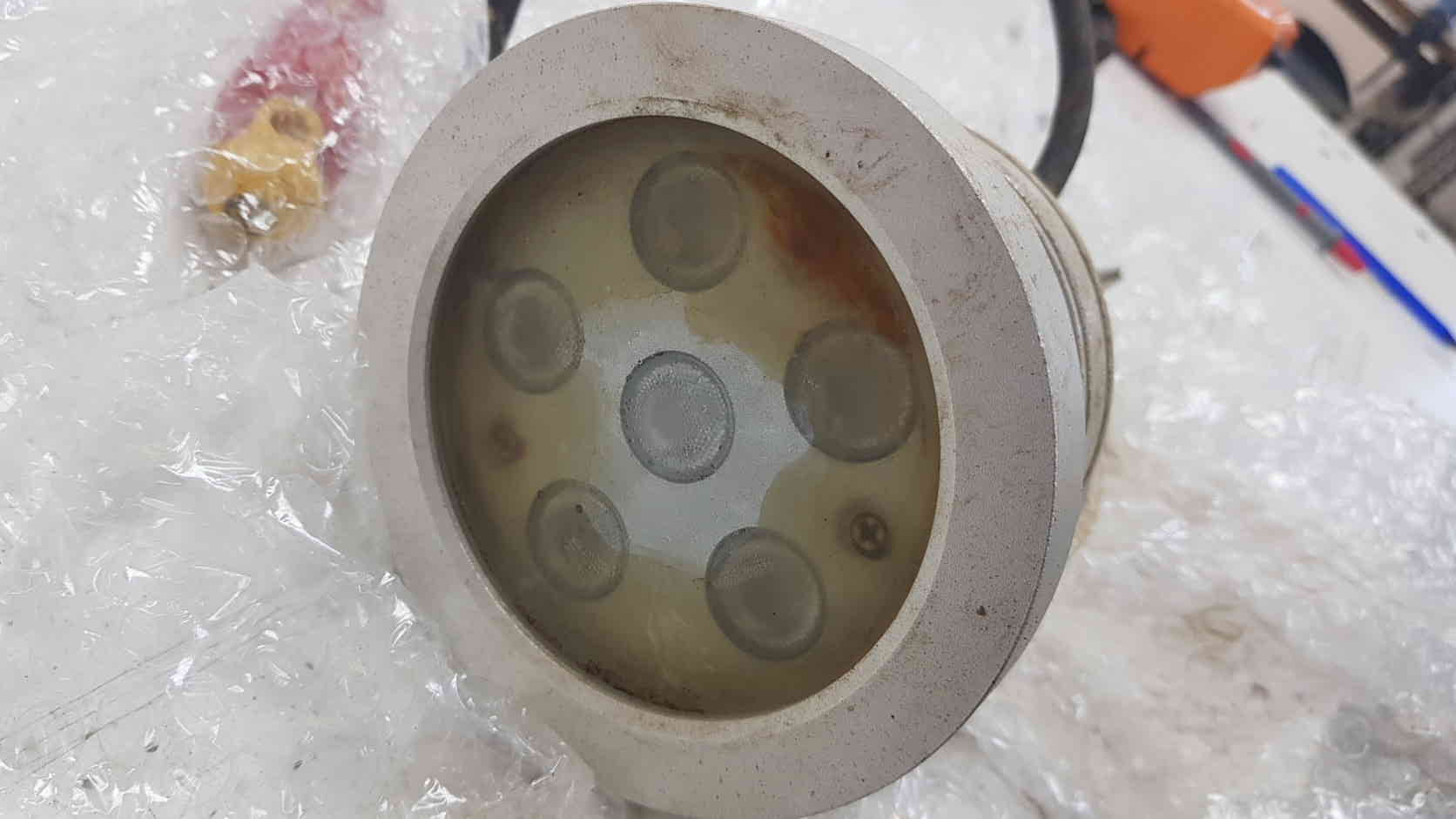
Materials age. Gaskets develop compression set; sealants harden or crack under UV, temperature changes and repeated movement.
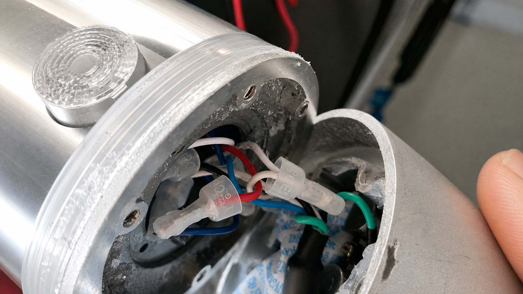
Every luminaire breathes. Heating and cooling change the internal pressure of the sealed housing, stressing weak interfaces over time.
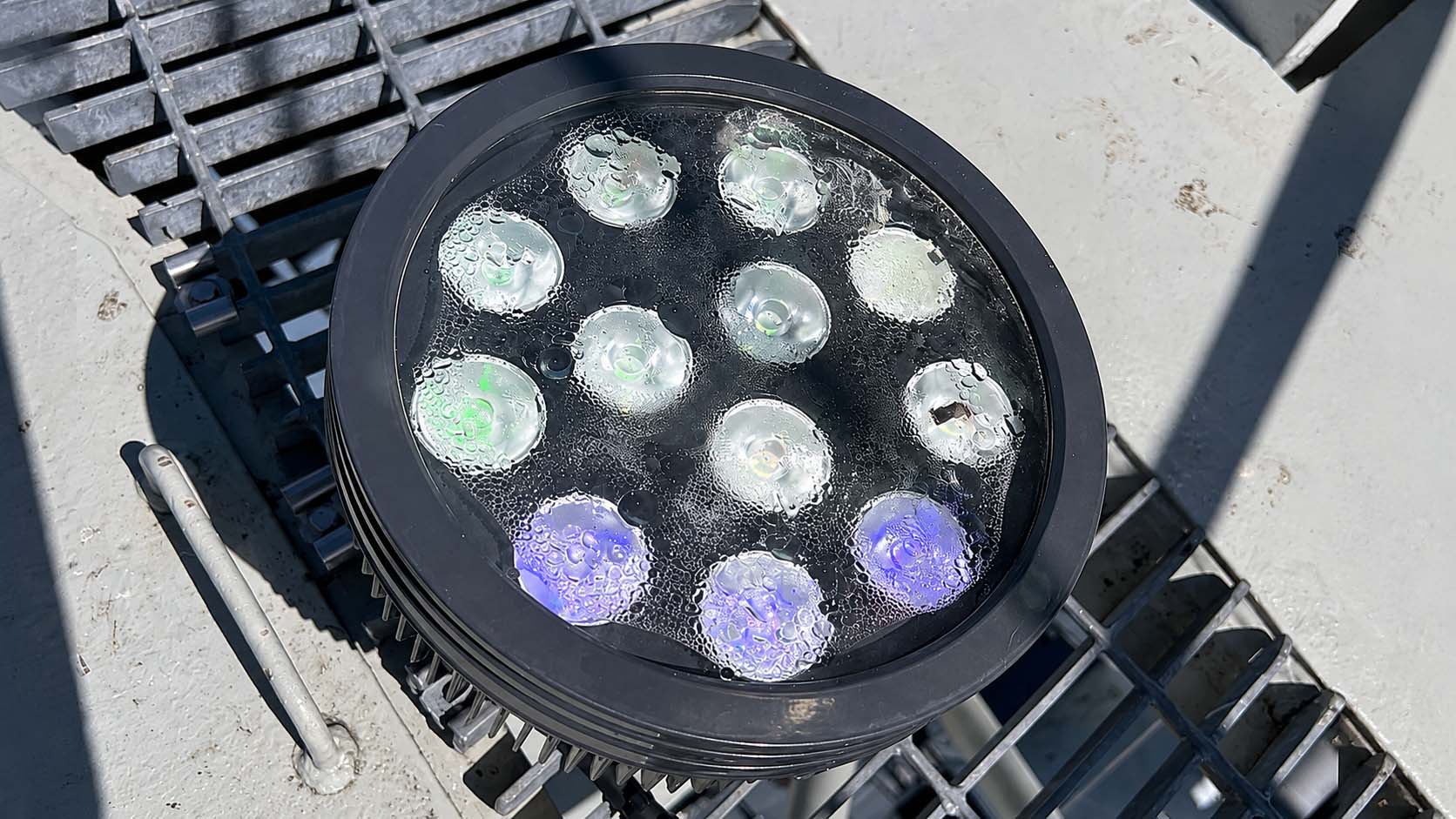
Process consistency. Sealant fill, curing and assembly tolerances decide whether the seal survives production and field life.
How a Gasket Seals
A silicone gasket seals not by blocking the gap but by deforming under compression and spreading sideways to fill the assembly clearance between the housing face and the end-cap face, creating a continuous band of physical contact. Tightening the end cap is not simply closing the door; it builds enough contact stress across that band to keep liquid water out.
Silicone is nearly incompressible, with a Poisson's ratio of about 0.49. Its volume barely changes under load, so the shape does — press it flatter and it must grow wider. This is the foundation for the groove-width rules later in this article. For the end-cap assembly, we control the press angle at 30°–40°. Too small an angle leaves insufficient deformation and contact stress; too large a shears the gasket locally, and that shear zone can crack over repeated thermal cycling.
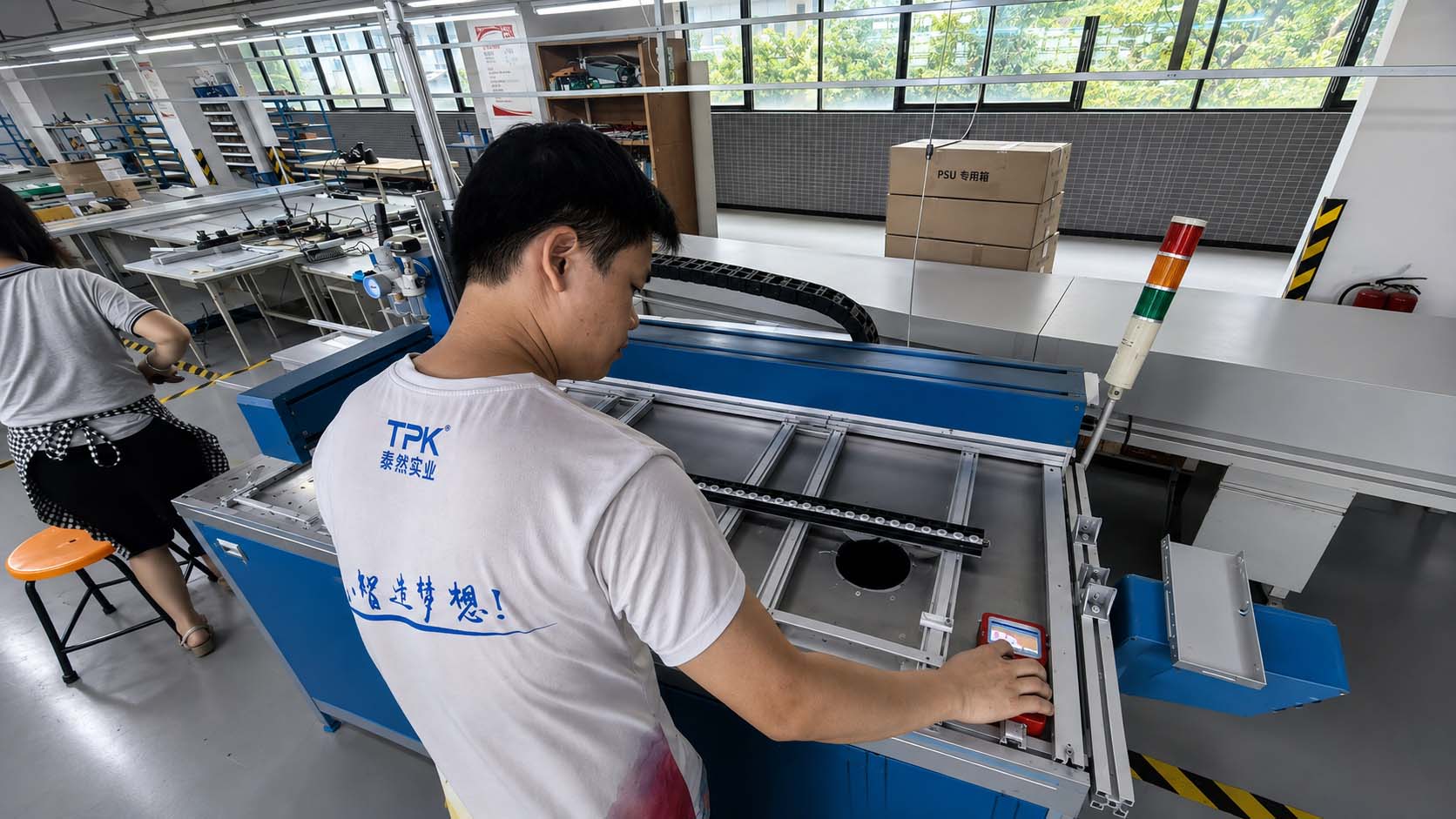
01 · Mix / dispense. Automated proportioning and a controlled dispensing path remove hand-mixing variation and keep the bead consistent.
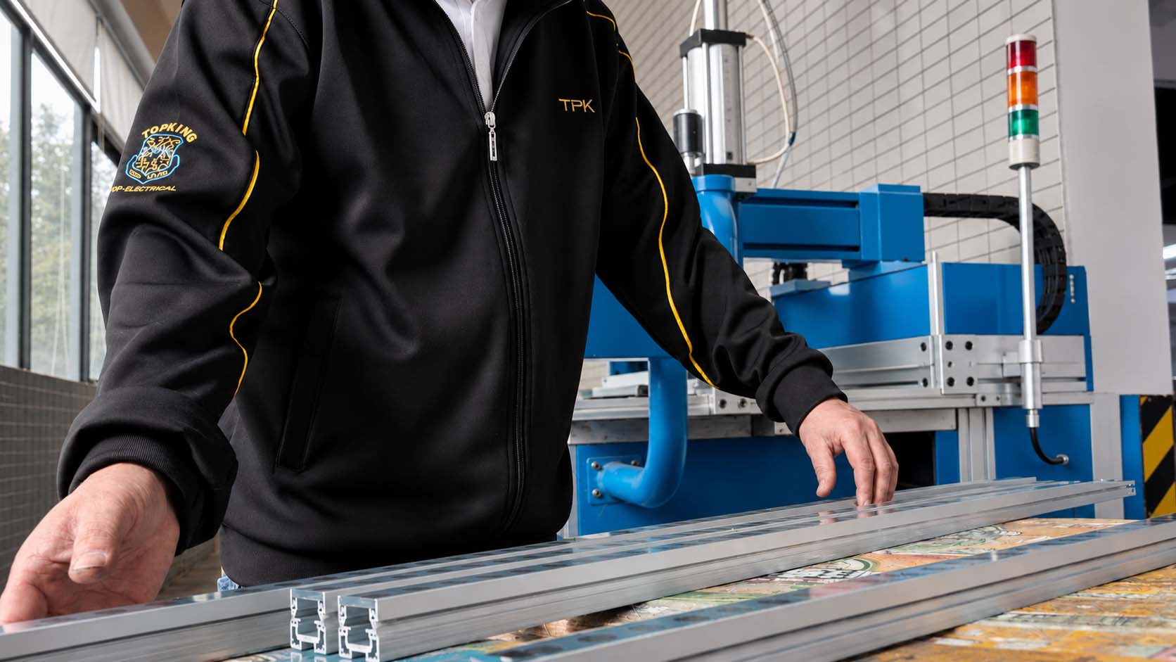
02 · Press the glass. Press the glass into the sealant bed while the material still has enough flow to wet out both surfaces.
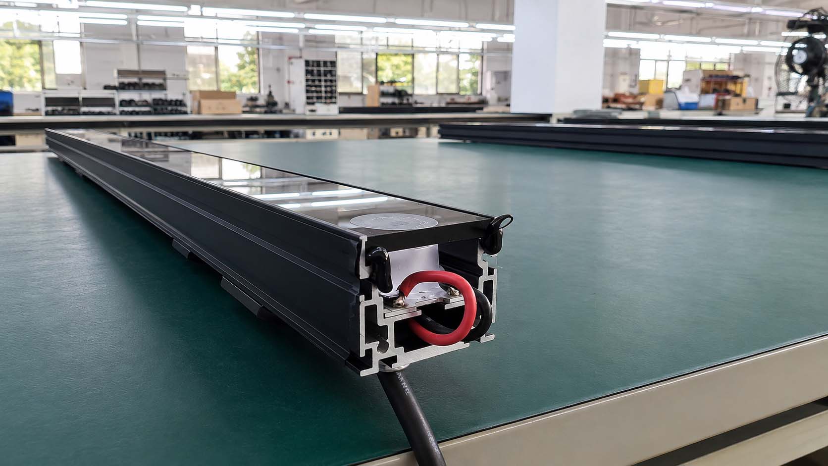
03 · Backfill both ends. The glass ends are one of the easiest places for a dispensing path to stop short.
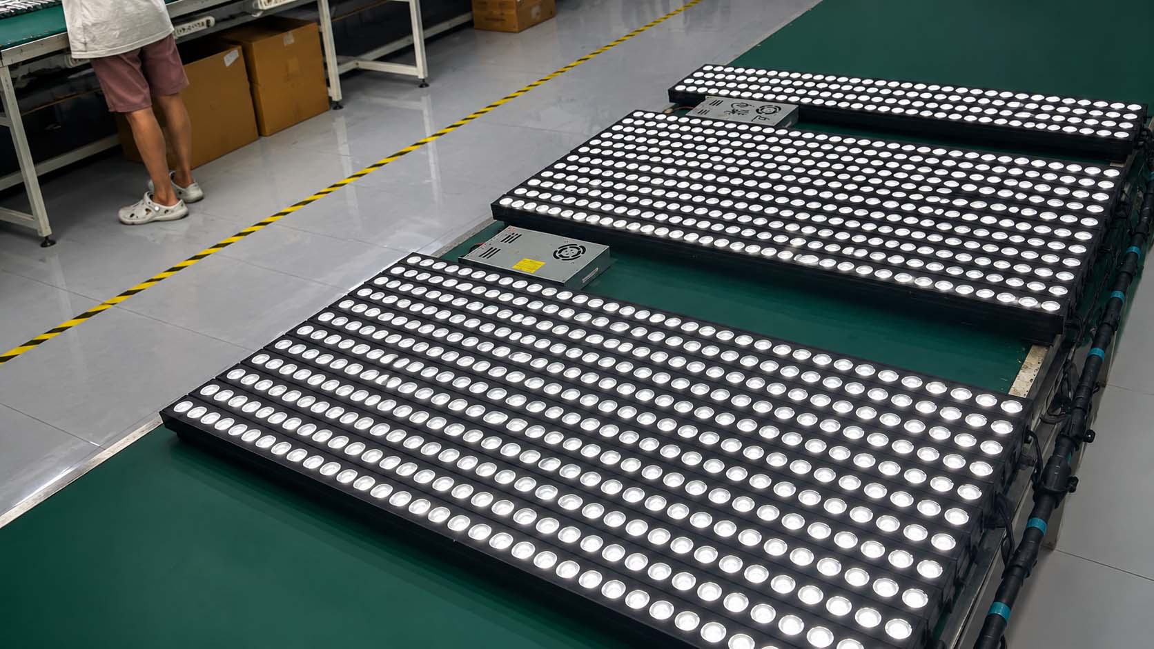
04 · Cure / age / final seal. Complete curing and full-power heat aging before final sealing reduce trapped moisture.
Material Aging Is the Real Long-Term Failure Driver
A new silicone gasket passes every factory QC check — fresh elastomer, adequate contact stress at 20%–30% compression, IP67 achieved. The question is whether it survives the UV, pressure swings and temperature extremes of a North American outdoor installation. That is where engineering experience shows.
Under sustained compression, the molecular chains of silicone creep, accelerated by heat. The measurable result is compression set: after being compressed for a long time, the gasket no longer returns to its original dimensions even when released. Inside the luminaire, the equivalent effect is a steadily falling recovery force and contact stress — until it drops below the minimum needed to seal and a leak path opens. This is why some luminaires are fine in year one and two, then start taking on water in year three. The material was decaying all along; it just crossed the threshold.
Ordinary rubber gaskets (EPDM or low-grade silicone) under sustained compression at 85°C can develop compression set above 30%–40% quickly, with a sharp loss of recovery force. After 500 hours of double-85 aging (85°C / 85% RH), cross-sections of such materials are visibly out of round and stay deformed when pressed. The gasket still looks like it is sealing, but the contact stress is no longer adequate.
Why Fumed-Silica-Reinforced Silicone
Fumed-silica-reinforced silicone uses fumed silica as the reinforcing filler, producing a higher cross-link density and a more uniform network structure than standard silicone. That shows up in several key parameters.
Tear strength is typically 30–50 kN/m, more than double that of standard silicone. This matters most on linear luminaires, for the reasons explained below.
Compression set can be held below 10% after long-term, high-temperature compression, versus 30%–40% for standard silicone — a three-to-four-fold difference. With the same groove design and the same initial compression, fumed-silicone gaskets lose contact stress far more slowly and stay sealed far longer.
Air tightness is also better: the denser network not only blocks liquid water but measurably slows the permeation of water vapour, which helps with glass fogging, even though the fundamental fix for trapped moisture remains humidity control in production.
The trade-off is cost — typically several times that of a standard silicone gasket. That is a real pressure on a cost-controlled product, but on wall washers and linear luminaires we have not found a workable substitute.
Linear Luminaires Face a Unique Shear Problem
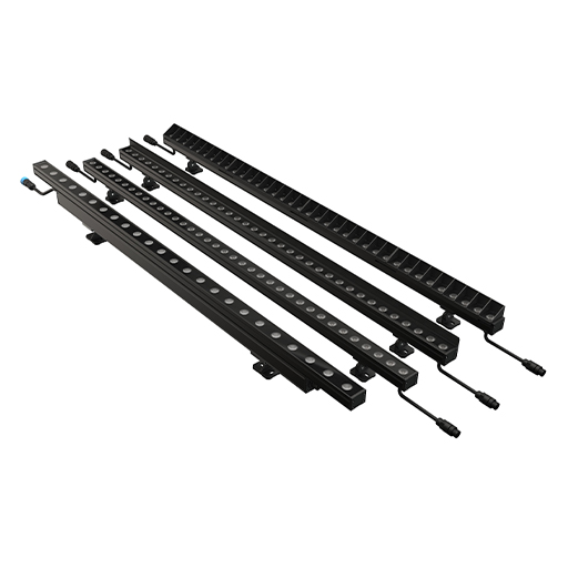
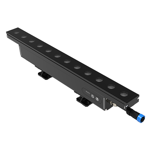
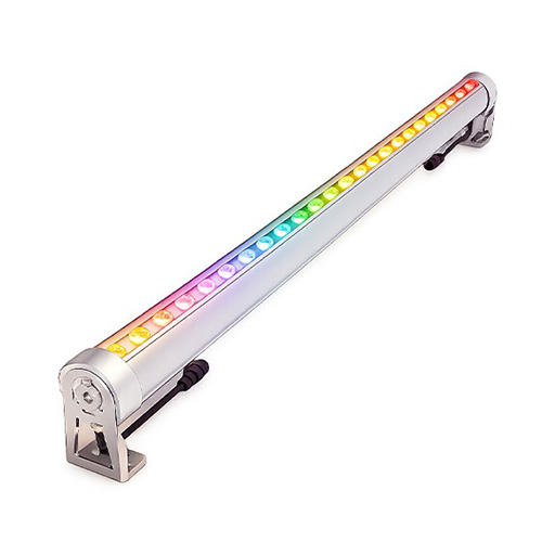
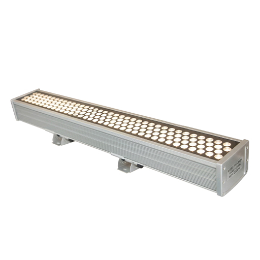
A round floodlight has a die-cast aluminium body, a symmetric structure and a small end-cap area; the gasket mostly sees axial compression. Linear luminaires are different. Wall washers and linear profile lights use extruded aluminium, whose linear coefficient of thermal expansion is about 23 × 10⁻⁶ /°C. A 1.2 m wall washer spanning a -20°C winter night to 60°C+ internal cavity under full load in summer — a swing of nearly 80°C — stretches by:
We design in roughly 2 mm of allowance at vertical and horizontal corner transitions. It serves two purposes: first, assembly tolerance — 2 mm of slack gives production a margin; second, the end caps impose strong lateral shear and friction on the gasket, especially at corners where expansion happens in four directions. That allowance extends gasket life, preventing the corner from being torn or worn by daily thermal cycling until the seal band turns from continuous to intermittent.
Why 20%–25% Compression
The industry nominal range for initial compression is 20%–30%. For the combination of fumed-silica-reinforced silicone on linear luminaires, our own experience caps it at 25% and recommends not exceeding that. Two reasons.
First, assembly load: the higher the compression, the more force the end cap needs. A linear end cap is typically held by a few M3 or M4 screws, and the thread cross-section is limited. Crank up the torque and the first thing that gives is not the end cap — it is the tapped thread in the aluminium extrusion. We have handled field cases where the complaint was a screw that would not tighten (slipping), when the actual failure was the thread being stripped by excessive axial load.
Second, stress relaxation: counter-intuitively, the higher the initial compression, the faster the rubber relaxes. Tighter is not safer. Over-compression accelerates fatigue and shortens life in hot, humid conditions. The 20%–25% band keeps initial contact stress sufficient while running stress relaxation at its slowest.
Groove Width and Fill Ratio
Because silicone is nearly incompressible, pressing a round cord to 75% of its original height (25% compression) keeps the cross-section area constant and forces the width up. A simple area-conservation estimate for a cord of diameter d: compressed height 0.75d, so width grows to roughly d / 0.75 ≈ 1.33d.
That is why the groove must be 1.25–1.3 times the gasket cord diameter — not as margin, but as room for the gasket to deform into. If the groove is exactly the cord diameter, the compressed gasket has nowhere to expand sideways; the side load transfers straight to the groove wall and can split a fumed-silicone gasket.
Fill ratio is the gasket cross-section area as a share of the groove cross-section area. Our requirement is no more than 85%, with 75%–80% recommended. The margin is not only for sideways deformation — it is also for thermal expansion. Silicone expands at roughly 300 × 10⁻⁶ /°C versus about 23 × 10⁻⁶ /°C for aluminium, a difference of nearly 13 times. A gasket that fits perfectly at room temperature can, at 85°C (double-85 aging or summer solar load), expand far more than the aluminium groove. If fill ratio is already 95% at room temperature, the expansion force pushes out through the groove side wall and lifts the end cap — we have seen this failure in double-85 testing, where the leak was not the gasket but a lifted end cap with a visible gap.
Three Materials, Three Tolerance Ranges
This is where linear luminaire designs most often go wrong. Body, end cap and gasket are made by different processes with tolerances on different scales:
| Component | Typical tolerance | Notes |
|---|---|---|
| Extruded aluminium body (wall / cavity) | ±0.15–±0.2 mm | Near the practical limit for extrusion. |
| Fumed-silicone gasket (moulded) | ±0.08–±0.1 mm | Moulded part; cord-diameter consistency. |
| CNC-machined / die-cast end cap (groove) | ±0.05 mm | Best achievable; groove depth and finish. |
Stacking the three together, the loosest combination (larger groove, smaller gasket) can drop actual compression well below the design value; the tightest combination can push fill ratio above 85%. Both limits must be calculated before drawings are released. Loosest: largest groove depth with smallest cord diameter — if compression falls below 15%, a batch of luminaires will leak in production. Tightest: smallest groove with largest cord — if fill ratio exceeds 90%, the end cap will be overloaded at high temperature. We once had a wall-washer batch pass lab validation and then come back with dozens of returns from a single lot; the extruded aluminium cavity tolerance had drifted wide, leaving insufficient compression. The worst-case check has been on every drawing since.
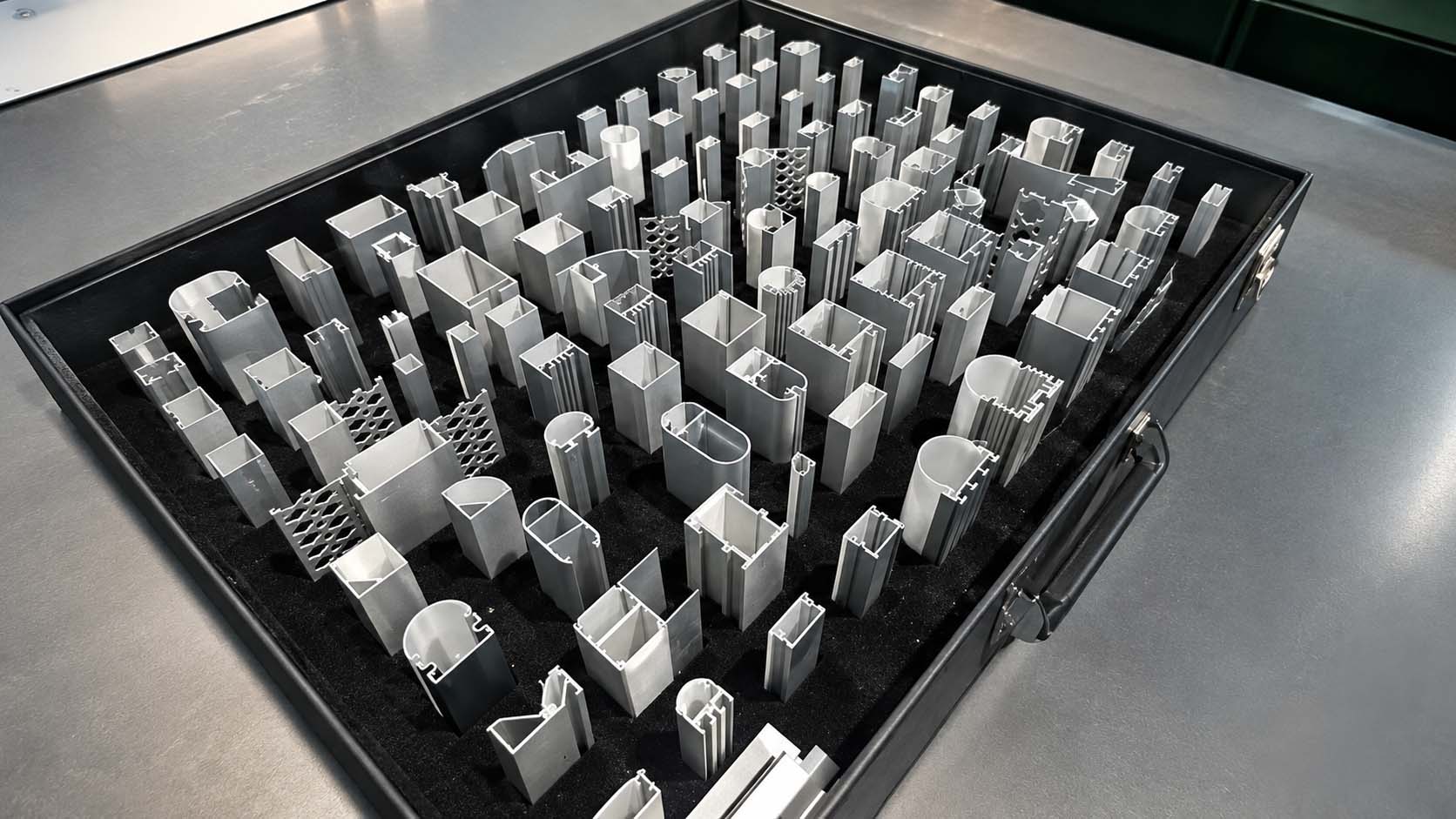
Housing and end cap. The body, end cap and gasket are made by different processes with tolerances on different scales — both worst-case combinations must be checked at the drawing stage.
Groove Surface Finish
One requirement often missing from drawings: the groove bottom that contacts the gasket (the sealing face) should be held to Ra 1.6–3.2. Finer (below Ra 0.8) is not a problem but costs more to machine. The real issue is too rough. Untreated die-cast surfaces and ordinary coarse machining run at Ra 6.3 or higher. On such a surface the gasket makes macro-scale contact, but the microscopic peaks and valleys form shallow channels. Liquid water's surface tension can hold them off, but in a high-humidity environment such as double-85 aging, water vapour molecules slowly migrate along those micro-channels — a fogging source that comes from the sealing face itself, not just from the cavity.
Putting this requirement on the drawing costs almost nothing: CNC parts already reach it, and a single facing pass on a die-cast part solves it. But if it is not written into the drawing, the purchased die-cast parts will almost certainly ship with the raw cast surface.
Validating Materials with Double-80 Aging
Do not validate a product with a project — the customer will not pay for your prototype. Run accelerated aging in the lab before and after pilot production, and verify material aging and weather resistance empirically rather than by theory. The industry-standard condition is double-80: 80°C and 80% relative humidity applied together. Under this condition chemical degradation and physical creep accelerate dramatically, exposing failure modes that would otherwise take years.
For pilot validation we run 100 hours of double-80, checking gasket recovery-force retention and compression set after the test to decide whether adjustments are needed before launch. New-product development is stricter: five samples per model run 500 hours of double-80, focusing on two things — whether the aluminium end cap and silicone gasket, with their very different thermal expansion coefficients, develop micro-relative displacement at the interface (which turns the contact band intermittent), and whether glass-to-sealant adhesion degrades enough to leak. Only after passing is the product released for pilot production, with third-party ETL or CE certification as an independent check of reliability before market launch.
ETL Certification Is a Starting Point
All regular-shipment products carry ETL certification, which US engineering projects commonly require — a basic entry ticket to the North American market. But ETL verifies electrical safety; its test conditions are not equivalent to the long-term waterproofing validation above. Certification is the starting point, not the finish line.
FAQ
Why do gaskets usually fail in year two or three rather than right after installation?
Gasket failure is a material-aging process. Compression set steadily reduces the gasket's recovery force and contact stress until it drops below the minimum needed to seal, and water ingress appears. That is why problems surface after one or two seasons of thermal cycling, not at the factory.
Why is 20%–25% compression better than 30% for fumed-silicone gaskets?
Higher compression loads the fasteners and accelerates stress relaxation. On narrow linear luminaires, M3/M4 screws can strip the aluminium thread before the end cap seals. The 20%–25% band keeps initial contact stress sufficient while slowing long-term relaxation.
Is an IP67 rating enough to guarantee outdoor reliability?
No. IP67 verifies static immersion resistance at one point in time. It does not cover years of thermal cycling, UV exposure and pressure swings. Material selection, compression and groove design, and accelerated aging validation are all required.