



Materials age
Gaskets, sealants and die-cast parts all change over time under temperature swings, UV exposure and mechanical stress.

Passing an IP test matters. The harder part is keeping a luminaire reliable after years of sun, rain, thermal cycling and material aging.
After more than 20 years of building outdoor luminaires, one thing has become very clear to us: long-term waterproofing never depends on one material or one test. What matters is whether design, materials, process control and validation work together as one system.
Gaskets, sealants and die-cast parts all change over time under temperature swings, UV exposure and mechanical stress.
Heating, cooling and sudden rainfall continually change the pressure inside the housing, gradually turning small weak points into real leakage paths.
Short sealant fill, incomplete curing, assembly tolerances and trapped moisture may be invisible at the factory, then surface months or years later outdoors.
When we open up returned luminaires, the problem is rarely as simple as “bad sealant.” More often, several small issues have added up: a gasket has lost recovery, the sealant has aged, the casting has porosity, the end cap is loaded unevenly, or thermal cycling has driven moisture into an already weak interface. That is why none of the controls below should be treated in isolation.
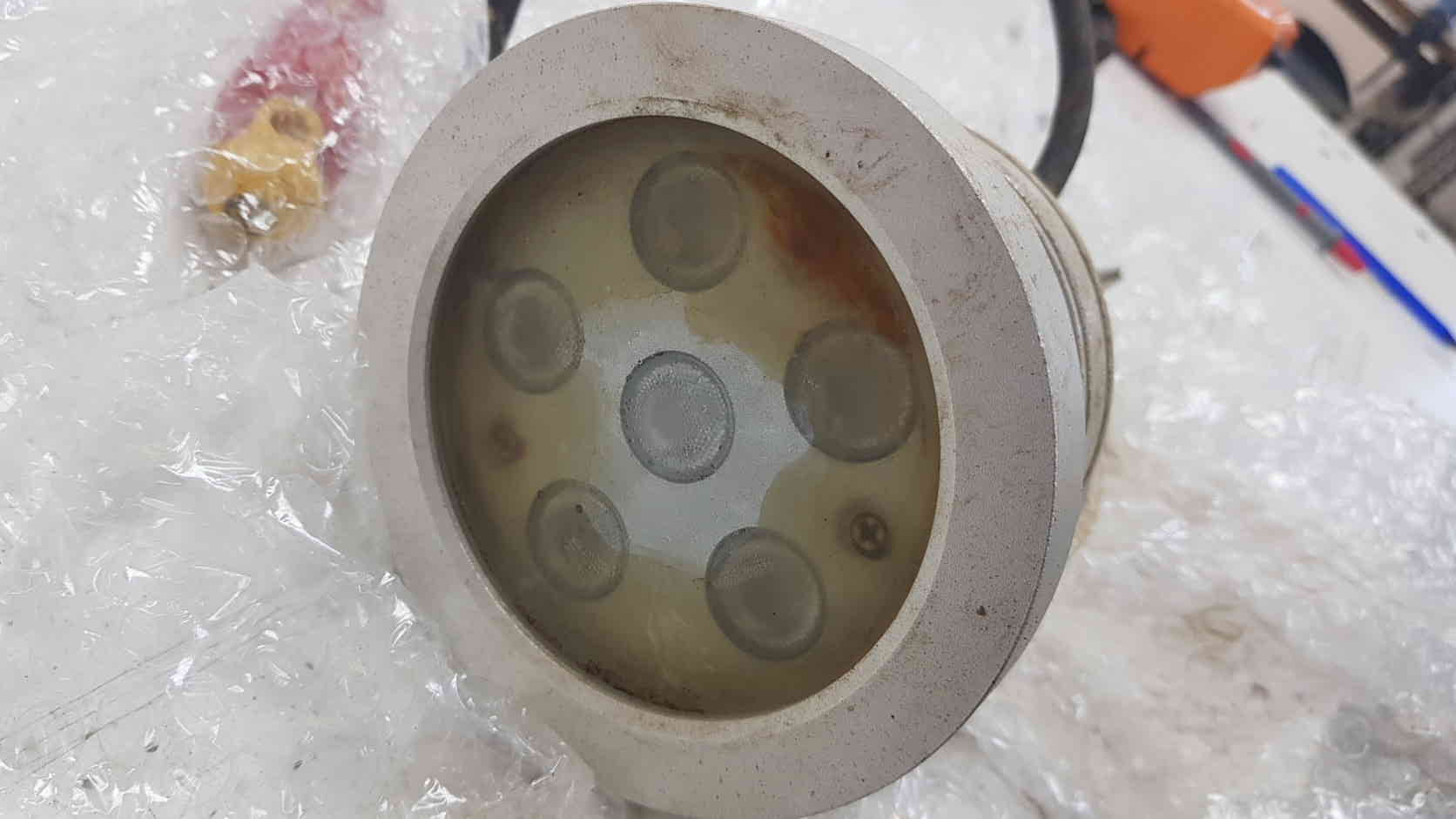
Gaskets develop compression set, while sealants can harden or crack under UV exposure, temperature changes and repeated movement.
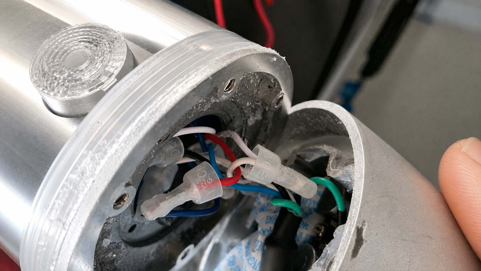
As the housing heats up, the air inside expands. When it cools, negative pressure develops and can pull moisture through weak interfaces.
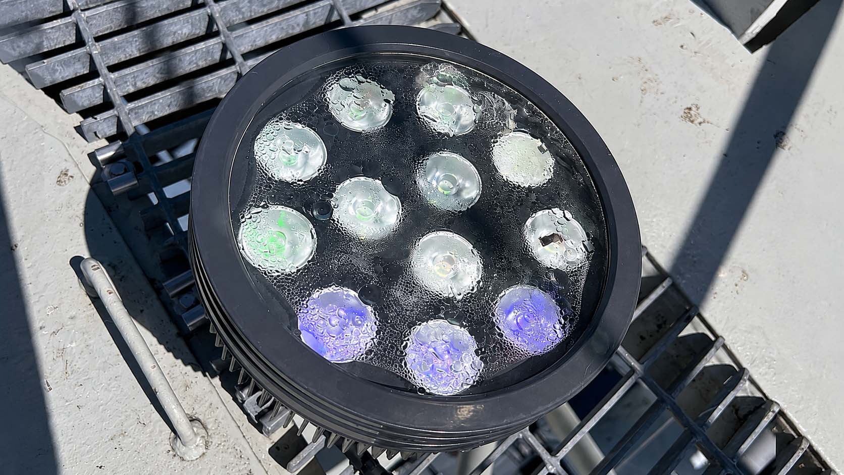
Short sealant fill at the glass ends, incomplete curing or residual moisture may not be obvious before shipment, but each can become a leak path outdoors.
Contamination in the aluminium casting process can leave internal porosity or pinholes that are invisible from the outside. If the wall is too thin, those defects can form a continuous path through the housing. Thermal cycling makes the problem worse because pressure changes can actively draw moisture inward. For this particular housing design, we keep the effective wall thickness at critical areas above 6 mm. That value comes from the structure itself and from lessons learned from past failures; a different housing design may require a different target.
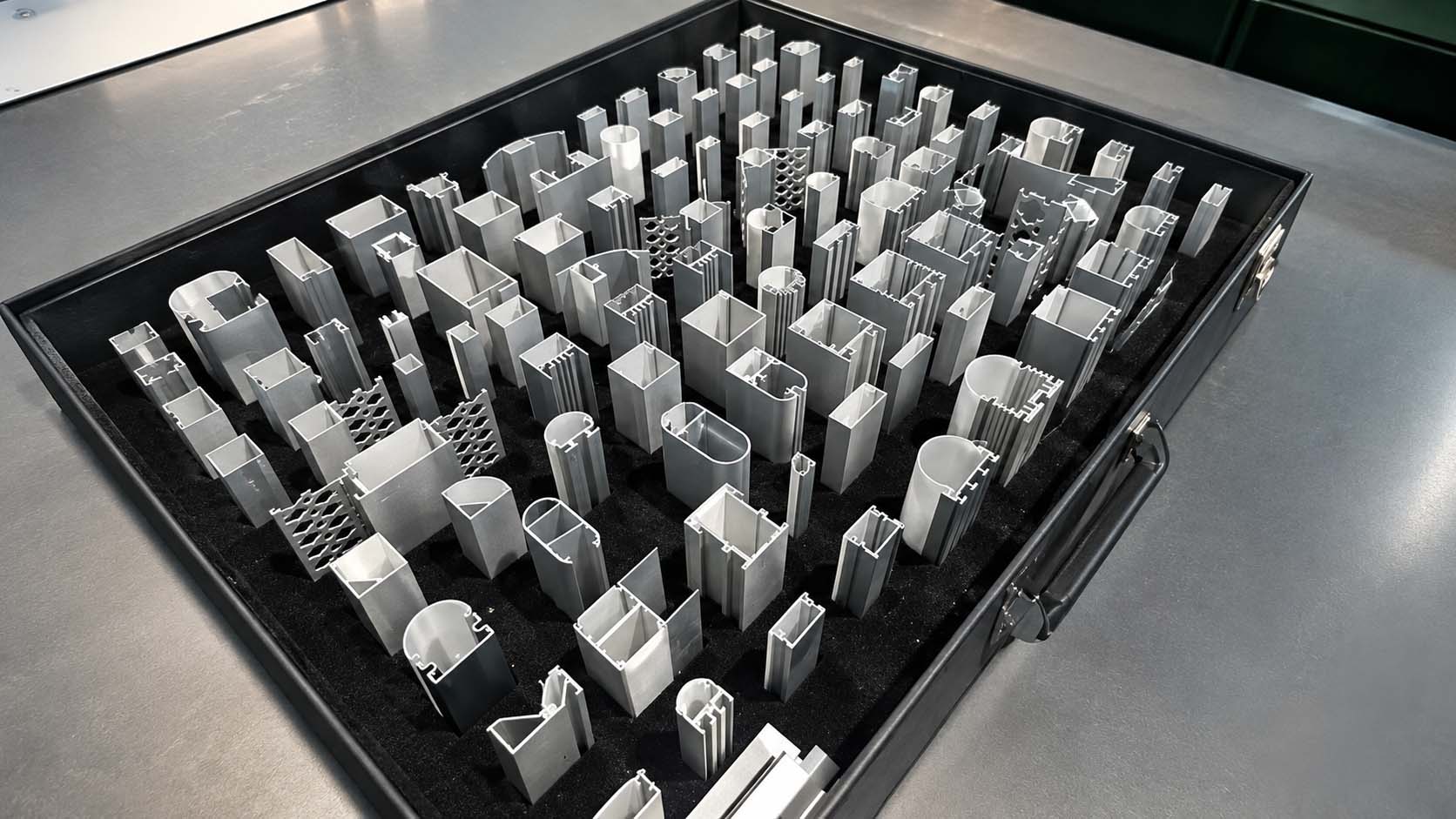
A silicone gasket works because it deforms under compression and spreads into the mating gap. For this end-cap design, we control the compression angle at 30°–40°. Too little deformation means insufficient sealing force; too much can introduce shear damage. After repeated thermal expansion and contraction, that damage can turn into cracking.
The fumed silicone rubber we use has a tear strength in the 30–50 kN/m range or higher, giving it far better resistance to tearing and edge damage than standard silicone compounds.
Its denser, more stable structure helps resist not only liquid-water ingress but also the gradual movement of humid air through weak sealing interfaces.
With a stable cross-linked structure, compression set can be kept below 10% under the specified long-term high-temperature compression conditions.
It is easy to assume that a gasket seals better the more it is compressed, which can lead designers toward 30% or even 35% compression. For narrow linear luminaires using fumed silicone rubber, our normal design target is 20%–25%. There are two practical reasons. First, the material is relatively firm and has strong recovery, so excessive compression can overload small M2 or M2.5 fasteners and threads. Second, over-compression accelerates fatigue in the elastomer and can shorten life under hot, humid conditions. Silicone is also nearly incompressible, with a Poisson's ratio of about 0.49, so compressing it vertically forces it to expand sideways. The groove therefore needs enough lateral space — typically around 1.25–1.3 times the gasket cord diameter for this design approach.
We normally target a gasket-to-groove fill ratio of about 75%–80% and avoid going above 85%. Silicone expands more with heat than aluminium. If the groove is already filled to 95% or more at room temperature, high internal temperatures or direct solar loading can generate enough expansion force to load the end cap unnecessarily.
This is one of the hardest parts of a narrow linear luminaire: the body is an aluminium extrusion, the end cap is die-cast or CNC-machined, and the gasket is moulded. Their manufacturing tolerances are nowhere near the same. During design, we therefore run a worst-case tolerance stack-up at both ends of the range — the loosest fit and the tightest fit.
| Component | Typical tolerance | Worst-case checks |
|---|---|---|
| Extruded aluminium body (wall / cavity) | ±0.15~±0.2 mm | Loosest condition: Pair the largest groove with the smallest gasket section and confirm that compression still reaches at least 15%. If it does not, part of the production run may end up under-compressed and vulnerable to minor leakage. Tightest condition: Pair the smallest groove with the largest gasket section and check that groove fill does not exceed 90%. If it does, thermal expansion can generate enough force to load the end-cap screws and threads. |
| Fumed silicone gasket (moulded) | ±0.08~±0.1 mm | |
| CNC / die-cast end cap (groove) | ±0.05 mm |
A sealed luminaire is a fixed-volume enclosure, so the air inside responds to temperature. Under direct sun or at full power, internal temperatures can reach 70–90°C. The air expands and the enclosure moves into positive pressure — the “exhale” part of the cycle. Later, a rapid temperature drop or cold rain on a hot fixture causes the air to contract, creating negative pressure that can reach roughly -10 to -30 kPa in severe conditions — the “inhale.” High-power floodlights are especially exposed because they run hot, and sudden rain can create a strong pressure swing. If the gasket has already aged or relaxed, that negative pressure can pull water or humid air through the weakest interface.
An ePTFE membrane separates liquid water from air by pore size and surface tension. The membrane contains billions of microscopic pores, typically around 0.1–1.0 μm, which block liquid droplets while allowing air and water vapour to pass through. This gives the enclosure a controlled path to equalize pressure before large positive or negative loads can build across the gasket.
When glass fogs soon after assembly, the cause is not always water coming in from outside. Sometimes moisture was trapped inside during production. If a fixture is assembled in a humid environment, that moisture can evaporate when the luminaire heats up and then condense on the inside of the glass as it cools. Incompletely cured adhesive can add volatile compounds to the same problem. Two-part sealants are particularly sensitive to mix ratio; even a small deviation can leave the cure incomplete, and thermal cycling can then drive gradual interfacial separation that may not become visible for 18–36 months.
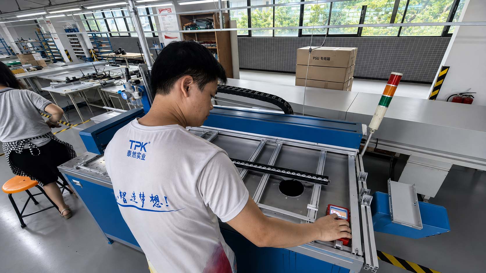
Use automated proportioning and a controlled dispensing path to remove hand-mixing variation and keep the bead volume and position consistent from one unit to the next.
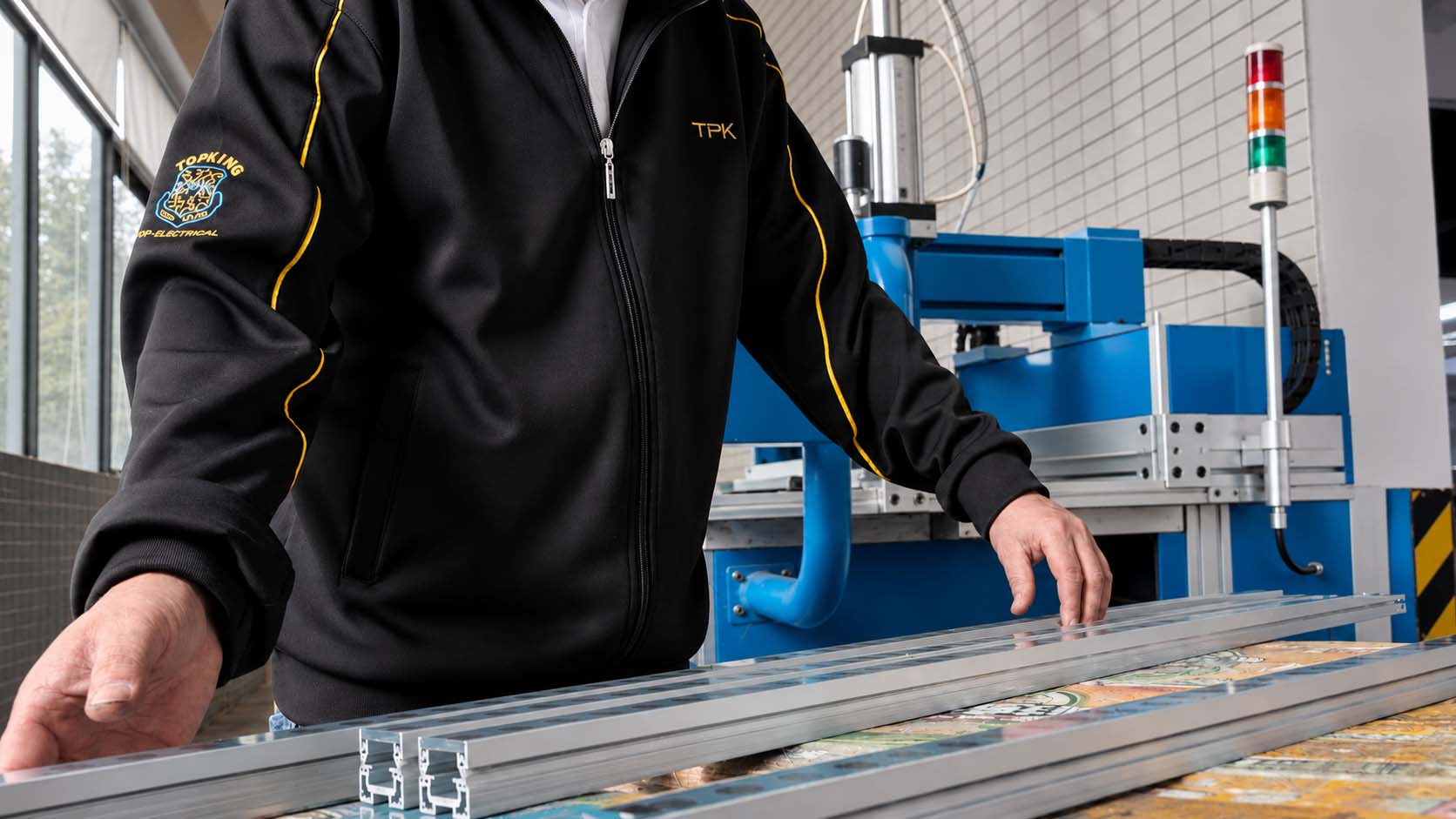
Press the glass into the sealant bed while the material still has enough flow to wet out both the glass and the groove surface.
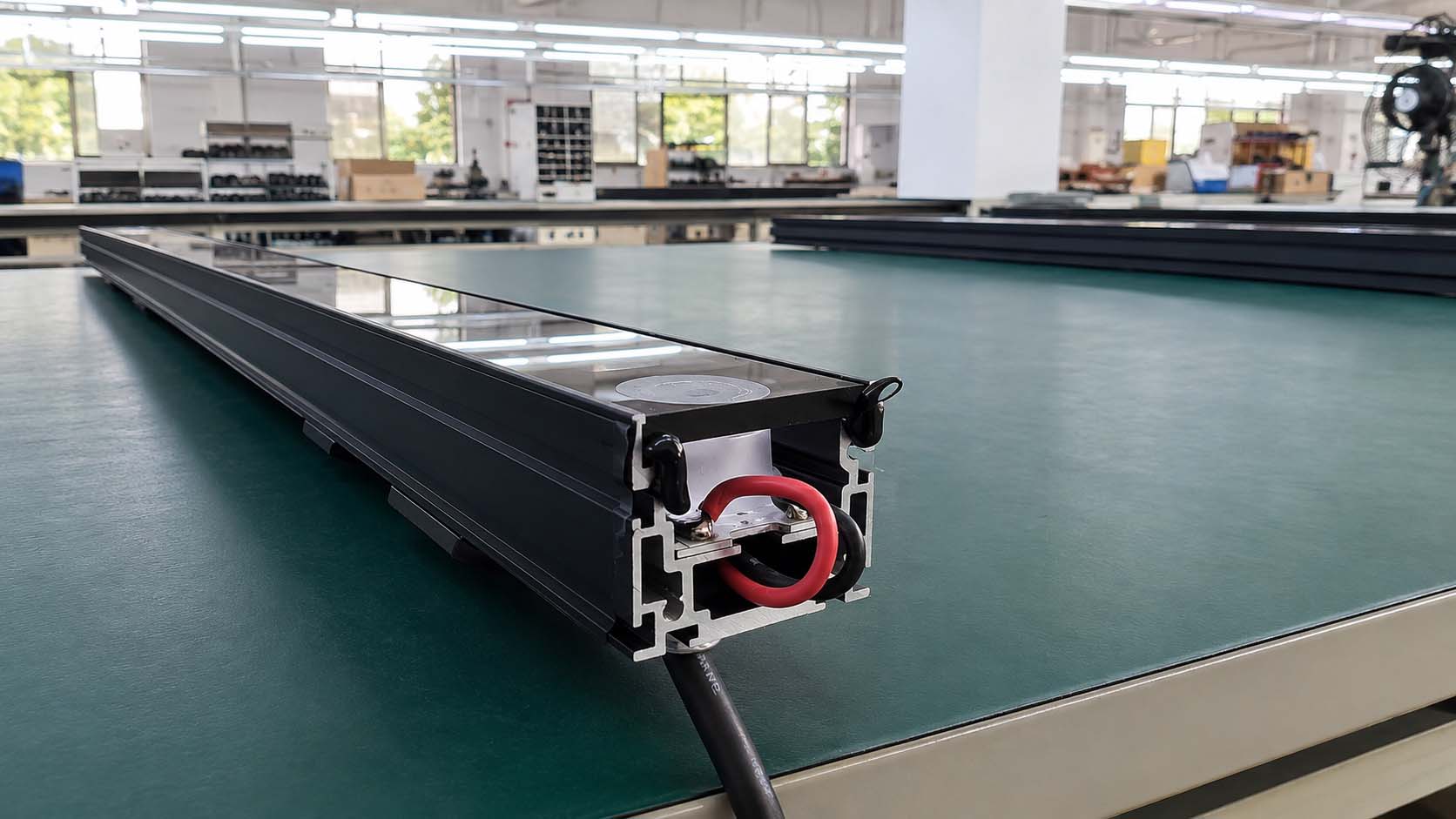
Use a scraper to pull sealant from the end-cap corner back toward the glass. This is one of the easiest places for a dispensing path to stop short and leave a small gap.
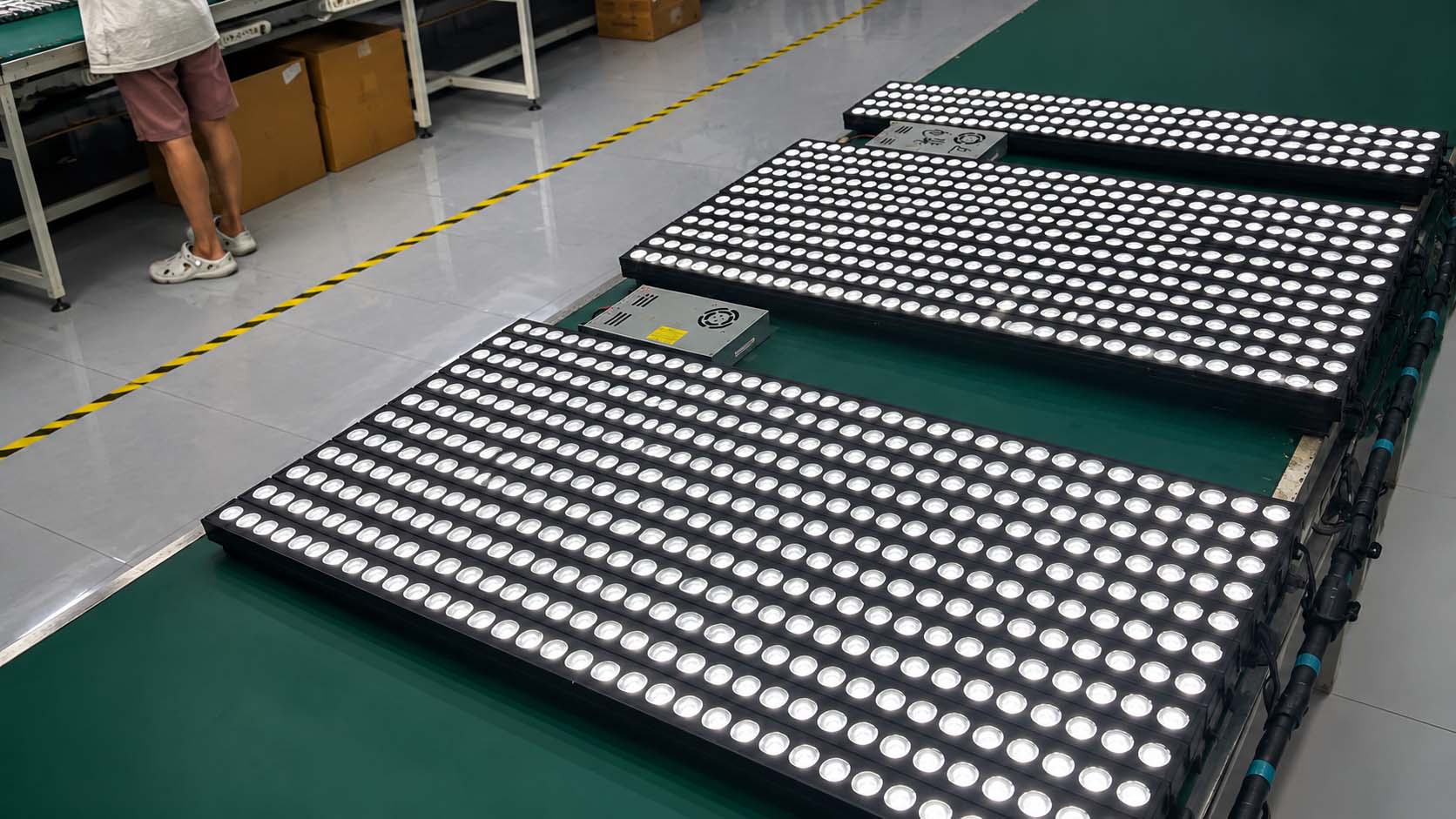
Allow the sealant to cure under controlled conditions and confirm full cross-linking before closing the end cap. Before final sealing, run the semi-finished luminaire at full power for two hours to drive out residual moisture and reduce humidity inside the cavity.
85°C / 85% RH is a widely used accelerated damp-heat aging condition. For production control, we run 500-hour checks by batch; during new-product development, five samples per model are put through 1,000 hours. We pay particular attention to micro-movement at the aluminium end-cap / silicone-gasket interface and to any loss of adhesion between the glass and sealant. The product does not move into mass production until the 1,000-hour validation is complete. Before shipment, waterproofing is not handled by sampling alone — every luminaire goes through three checks:
Run the luminaire at rated maximum power until thermal equilibrium so heat-related structural stress can expose weak points.
Immerse the hot luminaire for 30 minutes to reproduce the rapid pressure drop that can occur when a fully loaded fixture is suddenly exposed to cold rain.
After immersion, apply 20 kPa internal pressure and monitor pressure retention to detect very small leakage paths that may not be obvious from water testing alone.
Any failed unit is routed back for rework and kept out of the normal shipment lot. A leaking luminaire on site costs far more than the fixture itself — it can mean access equipment, labour, rework, delays and project claims.