W40 0-10V Series Development & Optimization
Technical Innovations, Dimming Consistency, and Process Upgrades
1. Development Background & Challenges
At the end of 2019, the product development of the W40 0-10V version was initiated. Initially, lengths L3, L6, and L12 could not guarantee the complete consistency of component parameters due to the power supply. This resulted in inconsistent minimum brightness and lighting times between products of the same or different lengths.
Through multiple tests and program adjustments, the minimum brightness difference for L3 and L12 was minimized. However, lighting time discrepancies remained. Furthermore, the power supply presented inventory and quality control challenges due to long delivery times, three different specifications, and difficult incoming material inspections.
2. Product Design & Key Features
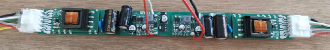
- Integrated Power & Control: 24V constant voltage power supply + 0-10V control driver integration. It uses the Jinshengyang 15W module, while L12 adopts a dual power supply scheme. Dimming parameters and consistency are decoupled from the power supply, enabling bulk storage.
- Advanced MCU: The 0-10V control driver board utilizes the new Nuvoton single-chip microcomputer (MCU) N76E003.
- High Precision Driver: The MBI6655 driver chip is modularly integrated. The dimming current consistency is strictly determined by the accuracy of the driver chip and the dimming resistance, ensuring an error rate of < 5%.
3. Technical Breakthroughs in Design
Theory and Method of Dimming Consistency
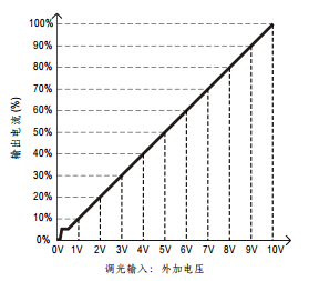
The voltage of the 0-10V dimming signal is detected by the AD pin of the MCU. The system continuously rolls and detects 15 groups of voltage data, eliminating the impact of voltage fluctuations using the arithmetic average value.
The dimming starting voltage of standard drivers varies (e.g., Ming Weft is 0.6V, others are 0.35V). Due to the weak pull-up resistance built into the 0-10V signal, the actual starting voltage fluctuates between 0.35V and 0.75V depending on connected power supplies. To avoid uneven dimming, our program sets the dimming signal threshold explicitly: when voltage > 0.31V, the lamp starts lighting with an initial brightness ratio of 0.4%.
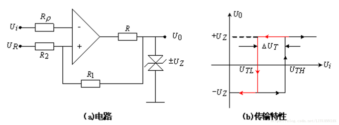
The Principle of Hysteresis Application
To prevent the lamp from repeatedly turning on and off around the 0.31V critical threshold, the program incorporates signal voltage hysteresis comparison processing. The lamp only turns off when the voltage drops below 0.19V. This maintains a voltage buffer width of 0.12V, completely solving stroboscopic (flickering) and out-of-sync problems caused by minor signal voltage fluctuations.
Hysteresis voltage ensures system stability. For example, if overvoltage protection is set at 100V, the system shouldn't cut off at 100.1V and instantly restart at 99.9V, which causes massive fluctuation. Setting a hysteresis voltage (e.g., restarting only when it drops to 90V) prevents this. In our lamps, the input must fall from the 0.31V start threshold down to 0.19V before extinguishing, guaranteeing reliable performance.
4. Product Performance Overview
| Product Model | Power | Dimming Signal | Lamp Bead | Bead Brightness | Temperature | PC Cover | Lens Angle | Whole Light Effect |
|---|---|---|---|---|---|---|---|---|
| LLS-COVE2-W40-8W-277V-016 (MCU) | 8W | 0-10V | Osram 3030 | 120-130LM | 3500K | Opal arch cover | 15° | 74 |
| LLS-COVE2-W40-30W-277V-016 (MCU) | 30W | 0-10V | Osram 3030 | 120-130LM | 3500K | Opal arch cover | 15° | 83.5 |
| LLS-COVE2-W40-8W-277V-016 | 8W | 0-10V | Philips 3030 | 160LM | 4000K | Opal arch cover | 15° | 80 |
5. Production Process Optimization
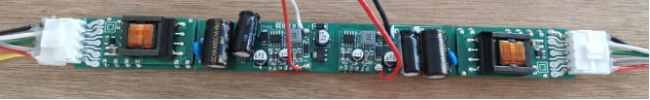
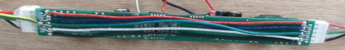
Integrated Modular Design: Utilizes a constant voltage power supply + control drive integrated solution. By combining the Jinshengyang module power supply with our self-produced low-voltage LED constant current driver board, the components are integrated into a single whole through pin welding and heat shrink sleeves.
Simplified Assembly: The welding work can be entirely completed in the electronics workshop. The input and output lines use 3.96 5P terminals, drastically simplifying the assembly process and eliminating wiring errors.

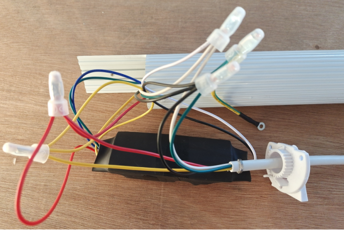
Complicated Wiring: The old constant current power supply scheme required a total of 6 lines (high voltage input, low voltage output, and light modulation). It used nylon wire caps, making the wiring operation complicated and prone to connection errors.
Hidden Dangers: After wiring, arranging the cables and plugging in the power supply was highly time-consuming, creating a hidden danger of wire breakage during operation.