


Hotel Facade Lighting: Window Spill Control and Curtain-Wall Integration
A practical engineering guide to coordinating hotel facade lighting around guest-room windows and tight curtain-wall reveals, resolving optical, mechanical, and electrical challenges through verified project examples.
1. Nighttime Architectural Identity: Creating a legible silhouette and structural hierarchy viewed from vehicular sightlines (100 m to 2 km) without turning the tower into an over-illuminated commercial billboard.
2. Obtrusive Light & Glazing Spill Control: Protecting guest comfort and sleep quality by restricting direct beam spill, secondary surface luminance reflections, and stray optical scatter across guest-room window glass.
3. Curtain-Wall Assembly & Constructability: Fitting compact linear luminaires, mounting hardware, electrical cabling, and drainage paths into tight architectural reveals—frequently within 30 to 35 mm pockets—while complying with applicable electrical codes (such as US National Electrical Code NRTL/ETL listing) and ensuring long-term serviceability at height.
This guide provides lighting designers, facade consultants, and contractors with an actionable engineering framework. It outlines an objective methodology for evaluating window spill, calculating true assembly clearances, coordinating low-voltage power distribution, validating nighttime operating scenes through 1:1 mockups, and preparing an airtight technical submittal prior to procurement.
1. Define the Lighting Task Before Selecting Fixtures
A recurring failure in hotel exterior lighting originates during the schematic phase: treating the building as a monolithic canvas and selecting luminaires from a single catalog family before establishing the visual tasks of each architectural zone.
1.1 The Conflict Between Skyline Definition and Vision Glass
On an architectural rendering, a building facade appears as an opaque, uniform solid. In reality, a hotel tower is composed of two conflicting materials:
- Opaque Architectural Elements: Concrete floor spandrel beams, aluminum composite panel (ACP) fascia, structural stone piers, and metal crowns that can absorb and reflect wash lighting.
- Transparent Vision Glazing: Double- or triple-glazed Low-E insulated glass units (IGUs) designed to allow daylight into guest rooms. Glazing cannot "hold" light; any luminous flux directed toward glass either transmits directly into the guest room as intrusive glare or reflects off coated surfaces as uncontrollable secondary scatter.
When lighting schemes specify broad floodlights or unshielded linear grazers along a facade without isolating these zones, light inevitably washes over the windows. The resulting interior glare triggers guest complaints, overrides blackout curtains, and compromises the hotel operator's brand standards.
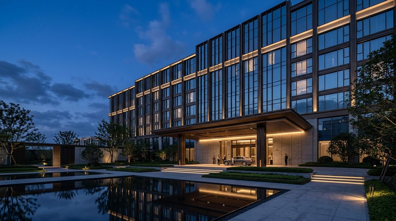
Concept Rendering — Facade Lighting Zoning: A balanced architectural night scene illustrating how tower structural definition, warm entrance porte-cochère downlighting, and low-level landscape illumination operate harmoniously with understated intensity.
- Slab-edge linear accents, vertical mullion grazing, crown wash.
- Viewing Distance: Highway & Skyline (100 m to 2 km).
- Engineering Boundary: Strict optical cutoff at vision glass boundaries.
Zone 2: Arrival & Drop-Off (Porte-Cochère & Entrance Canopy)
- Low-glare threshold illumination, column accents, warm soffit downlights.
- Viewing Distance: Vehicular approach & Pedestrian threshold (0 to 50 m).
- Engineering Boundary: Human eye-level shielding; zero high-angle glare.
Zone 3: Resort Grounds & Landscape (Secondary Ambient Layer)
- In-ground uplights, low pathway bollards, courtyard planter accents.
- Viewing Distance: Seated or strolling guests within outdoor terraces.
- Engineering Boundary: Soft, low-illuminance backdrop; never outshines tower.
1.2 Delineating the Three Lighting Layers
To prevent functional conflicts, project teams should systematically separate the hotel exterior into three distinct lighting layers:
- The Tower Facade (Layer 1): The primary task is architectural definition—tracing horizontal floor plates, grazing vertical fins, or accenting the tower crown. Illumination should be restricted to opaque structural zones. Typical luminaires include compact exterior linear lightbars (LLS-OP-W30C Series) embedded in slab-edge reveals, narrow-beam wall washers (LWW-WZB-W55), or high-power vertical projectors (LWW-OP-W75).
- Arrival and Drop-Off (Layer 2): The porte-cochère and entrance lobby transition guests from dark exterior roadways into the illuminated interior. At close range (under 50 meters), human eyes look directly toward facade surfaces. Unshielded floodlights or reflective wall grazing will blind approaching drivers and produce discomfort for arriving guests. Luminaires here require deep physical cutoffs, micro-prismatic diffusers, and warm correlated color temperatures (typically 2700K to 3000K).
- Resort Grounds and Landscape (Layer 3): Grounds lighting—pathways, courtyard trees, water features, and perimeter planters—must serve as a low-brightness supporting layer. If courtyard planting is illuminated brighter than the tower base, the architectural hierarchy collapses.
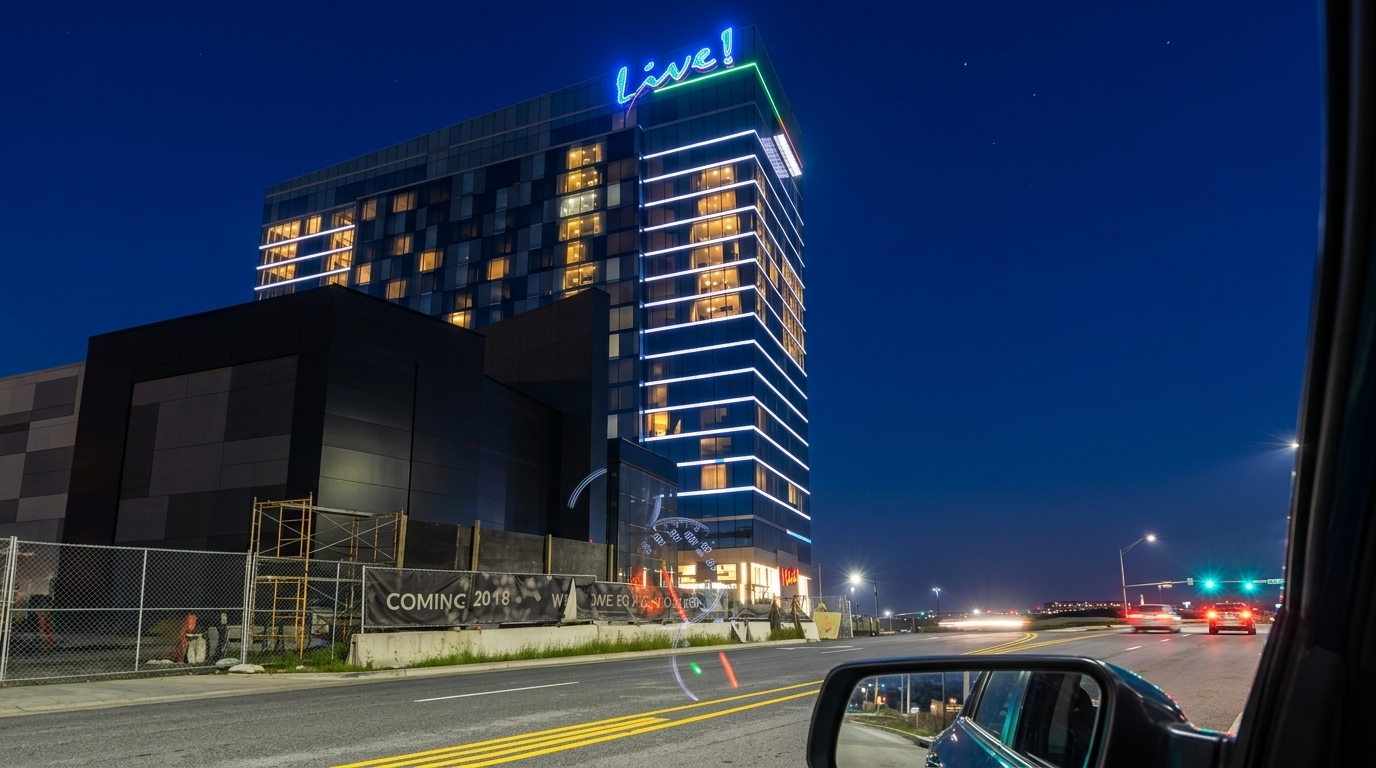
Layer 1 (Tower Facade): Slab-edge linear accent grazing on the Live! Casino & Hotel tower, demonstrating strict vertical beam cutoff at guest-room vision glass boundaries.
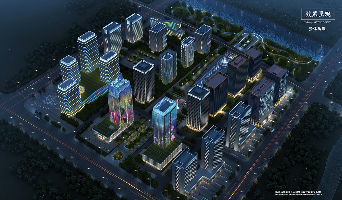
Layer 2 (Podium & Arrival): Flush-concealed linear illumination at the Linhai Business Headquarters, providing low-glare visual guidance without high-angle flare into windows.
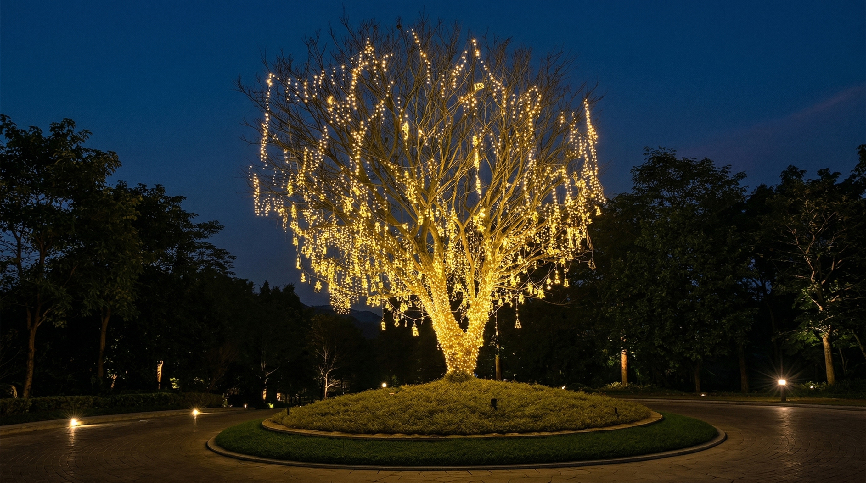
Layer 3 (Resort Grounds): In-ground uplights and pathway accents at the New World Hotel Qingyuan, creating an intimate landscape ambient layer that never outshines the facade.
1.3 Chapter Output: The Facade Zoning Audit
Before requesting product samples or running lighting simulations, the design team should prepare a Facade Zoning Drawing:
- Mark all Target Surfaces (spandrels, fins, crown) in green;
- Mark all Unlit Zones (guest-room vision glass, operable windows, private balconies) in red;
- Identify primary Observer Coordinates (approaching roadway, arrival porte-cochère, seated courtyard, and interior guest bed positions).
2. Control Window Spill Through Optics, Position and Aiming
When a client or facade consultant raises concerns about light entering guest rooms, a common response is simply to recommend a narrower nominal lens, such as "changing from 30° to 15°." On a completed building, this adjustment alone often fails to solve the issue.
2.1 The Three Mechanisms of Glazing Intrusion
Unwanted light trespass into guest rooms occurs through three distinct optical mechanisms:
- Direct Beam Spill: Stray flux emitted outside the nominal beam angle that directly enters the window aperture due to lens dispersion or unshielded LED packages.
- Secondary Surface Luminance: Light reflected diffusely from an illuminated architectural spandrel back into adjacent glazing. High-reflectance white granite, polished marble, or light-colored ACP panels can generate significant ambient brightness immediately outside the glass pane.
- Specular Reflection from Curtain-Wall Glass: Modern architectural glazing utilizes double- or triple-glazed Low-E coatings. At high angles of incidence (particularly beyond 60°), coated glass acts as a partial mirror. A vertical grazing luminaire aimed down a mullion can reflect intensely into opposing corner windows or adjacent balcony glazing.
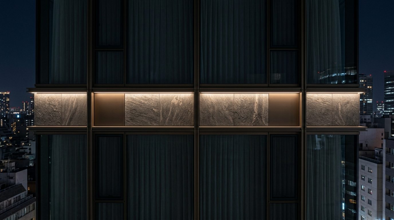
Glazing Cutoff — Concept Rendering: A gentle warm grazing wash on the horizontal spandrel panel between floors, engineered with a steep optical cutoff that leaves guest-room vision glass above and below completely unlit and dark.
2.2 Beam Angle (FWHM) vs. Field Angle and Stray Flare
In photometric engineering (ANSI/IES LM-63), the Beam Angle is defined strictly by the Full Width at Half Maximum (FWHM)—the angle between the two directions where luminous intensity drops to 50% of peak intensity (Imax).
However, the human eye adapts logarithmically to darkness:
- The Field Angle measures the spread down to 10% of Imax, containing luminous flux that can illuminate surfaces far outside the target beam.
- Beyond the field angle, unshielded secondary lenses emit peripheral flare at low percentages of peak intensity. In a dark night environment, even low-intensity light directed toward a guest bed can be glaring, disrupts sleep, and causes guest dissatisfaction.
Therefore, a specification stating "15° beam" does not guarantee zero window spill. Cutoff must be verified across the entire polar candela curve.
2.3 The Combined Role of Mounting Offset, Aiming Tilt, and Shielding
Controlling spill light requires balancing three physical parameters in unison:
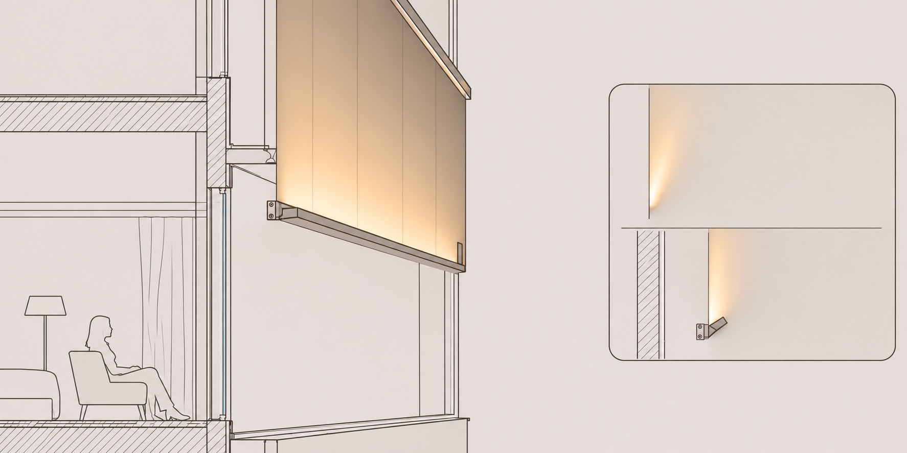
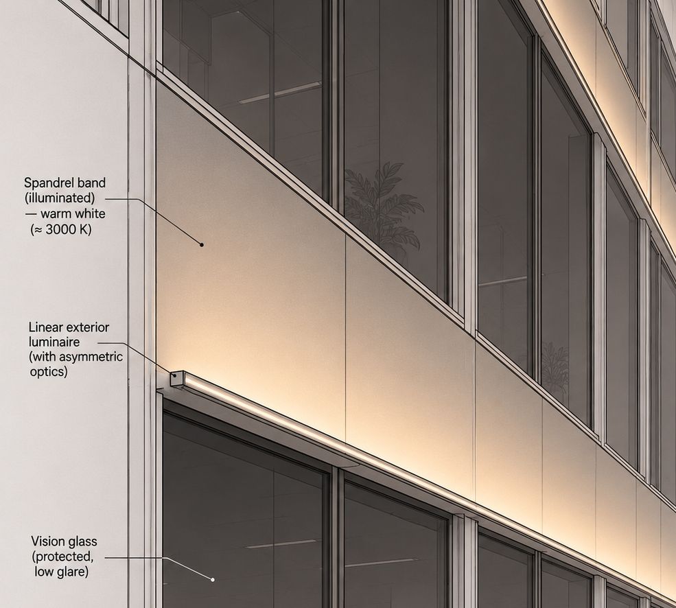
Asymmetric Optical Distribution: Utilizing asymmetric lenses (e.g., 15°×55°) directs peak luminous flux forward and upward along the spandrel band, while maintaining a steep cutoff on the rear edge facing the vision glass.
Mounting Setback & Aiming Tilt: Calibrating setback distance (S) and tilt angle moves the luminaire outward, enabling physical shielding accessories to block direct lines of sight from guest windows below.
- Mounting Setback (S) and Offset: Moving the luminaire outward from the glazing boundary changes the angle of incidence. An offset allows physical shielding accessories to block the direct line of sight from the window below.
- Asymmetric Optical Distribution: Utilizing asymmetric lenses (such as 15° vertical by 55° horizontal) directs peak luminous flux forward and upward along the spandrel band, while maintaining a steep cutoff on the rear edge facing the vision glass.
- Internal Micro-Louvres vs. External Visors:
- Internal Honeycomb / Blade Louvres: Factory-installed matte-black baffles positioned beneath the front glass cover. They absorb lateral wide-angle scatter before light exits the housing, cutting high-angle flare without altering the fixture's exterior envelope or IP rating.
- External Cowls / Snoots: Used when architectural reveals cannot accommodate internal louvres, providing a physical barrier against direct sightlines from interior guest spaces.
2.4 Aligning Photometric Data with Actual Configurations
A frequent source of submittal rejection occurs when a contractor submits an IES photometric file measured from a standard bare-lens luminaire, but requests factory installation of an internal honeycomb louvre.
Internal louvres absorb stray scatter and reduce total luminaire optical efficiency while significantly modifying the candela distribution curve. Photometric calculations in DIALux evo or AGi32 must utilize IES files generated from the exact combination of LED binning, optical lens, and internal louvre accessory specified for the project.
2.5 Evaluating Spill Light: CIE 150:2017 Evaluation Framework
Rather than relying on unachievable slogans like "zero light trespass," project specifications should adopt the objective evaluation framework of CIE 150:2017 (Guide on the Limitation of the Effects of Obtrusive Light from Outdoor Lighting Installations).
| Environmental Zone | Typical Application Setting | Max. Vertical Illuminance on Glazing (Ev) [Pre-Curfew] | Max. Vertical Illuminance on Glazing (Ev) [Post-Curfew] | Max. Source Intensity (I) [Post-Curfew] |
|---|---|---|---|---|
| E1: Intrinsically Dark | National parks, rural eco-resorts, dark-sky reserves | 2 lx | 0.1 lx | 0 cd |
| E2: Low District Brightness | Rural and outer suburban resorts | 5 lx | 1 lx | 500 cd |
| E3: Medium District Brightness | Suburban commercial, urban hotel districts | 10 lx | 2 lx | 1,000 cd |
| E4: High District Brightness | High-density city centers, entertainment/casino districts | 25 lx | 5 lx | 2,500 cd |
2.6 Chapter Output: The Optical Submittal Rule
The design team should not approve an optical submission based on nominal angles alone. The contractor should be required to submit:
- An IES photometric file matching the exact luminaire housing, CCT, secondary lens, and internal louvre accessory;
- A 3D photometric calculation demonstrating that vertical illuminance (Ev) across the exterior guest-room window plane meets the project's specified CIE 150 environmental zone limit;
- Confirmation of mounting setback and tilt coordinates on architectural section drawings.
3. Verify the Complete Curtain-Wall Installation
In high-rise hospitality architecture, linear luminaires are rarely mounted on exposed open surfaces; they are concealed within architectural reveals, slab-edge curtain-wall pockets, or structural transom channels to maintain an uncluttered daytime appearance.
3.1 The Total Assembly Envelope
The available curtain-wall pocket represents a hard boundary. To determine whether a luminaire truly fits, the team must examine the complete assembled cross-section:
Assembly Depth Envelope = Hhousing + Hbracket + Hfastener
- Hhousing: Nominal luminaire body height (e.g., 30.0 mm). (Product specification)
- Hbracket: Thickness of the mounting clip base (e.g., 2.0 mm). (Hardware specification)
- Hfastener: Screw head profile. If a standard pan-head screw is used directly beneath the fixture body, the fastener head adds to the stack, creating dimensional interference in a 32 mm cavity.
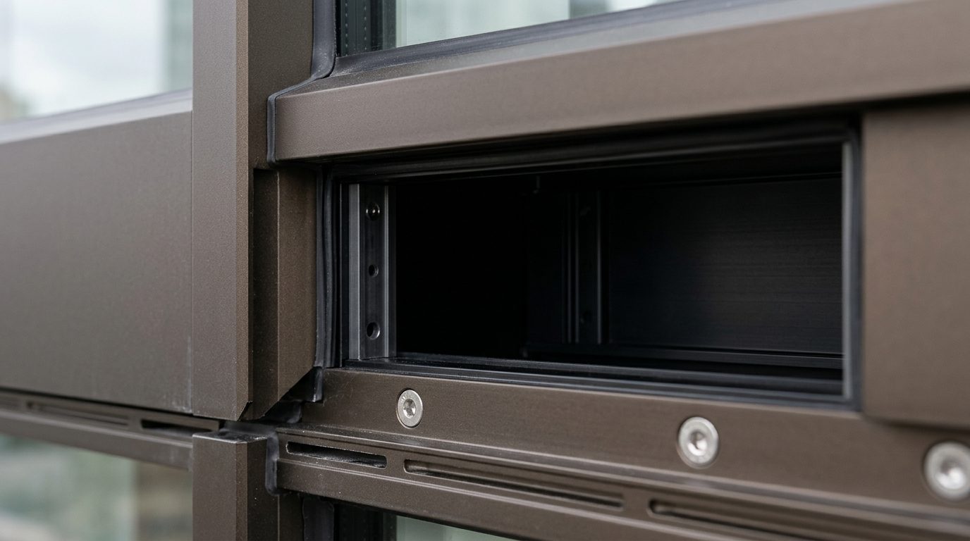
Curtain-Wall Slab-Edge Reveal Pocket: A high-precision aluminum transom extrusion showing a clean, vacant ~32 mm (1.25-inch) reveal slot with recessed countersunk fasteners and lateral drainage weep paths, engineered for modular luminaire integration.
"The tender specifies a maximum housing height of 25 ±5 mm (excluding the mounting bracket), which means the acceptable maximum height is 30 mm. Therefore, a 31 mm housing height is outside the permitted tolerance."
This record demonstrates that consultants enforce cavity limits strictly; a 1 mm variance beyond tolerance can lead to outright rejection.
3.2 Case Study 1: Live! Casino & Hotel Maryland — The 1.25" (32 mm) Slab-Edge Constraint
The Live! Casino & Hotel Maryland Project illustrates how project-specific engineering resolves tight cavity integration.
- Project Scale & Condition: High-rise hospitality property with 860 linear fixtures installed across 16 floors on three elevations (West, North, South).
- The Hard Constraint: Luminaires had to seat within a recessed metal cavity in the curtain-wall slab edge. Available cavity depth was exactly 1.25 inches (~31.75 to 32.0 mm). The architect's submittal review noted: "Confirm fixture and angle mounting method will fit within 1.25″ cavity."
- The Engineering Solution:
- Profile & Mounting: Deployed the LLS-OP-W30C platform featuring a 30×30 mm aluminum body. To fit the 32 mm depth, custom flat aluminum mounting clips were engineered with countersunk screw recesses, allowing the assembled depth to sit within tolerance.
- Tempered Glass Lens: Earlier generations used polycarbonate diffusers. In long-term outdoor high-rise service, UV exposure can cause polycarbonate yellowing and micro-crazing. The 2024 upgrade specified tempered optical glass, ensuring long-term color stability.
- Three Coordinated Lengths: The West elevation featured long runs (517.5" per floor), while North and South elevations tapered from 40" at upper floors to 35" at ground level. Three coordinated lengths sharing identical profiles, connectors, and 24V inputs were deployed: LLS-OP-W30C-L12 (1,219 mm / 48", 15W RGB, 692 units), L6 (610 mm / 24", 8W RGB, 105 units), and L3 (305 mm / 12", 4W RGB, 63 units).
- US NEC Code Compliance: Under the US National Electrical Code, CE marking is not recognized for permanent building wiring. The fixtures carried authentic NRTL Listing (ETL by Intertek) tested to UL standards, ensuring approval by the local electrical inspector.
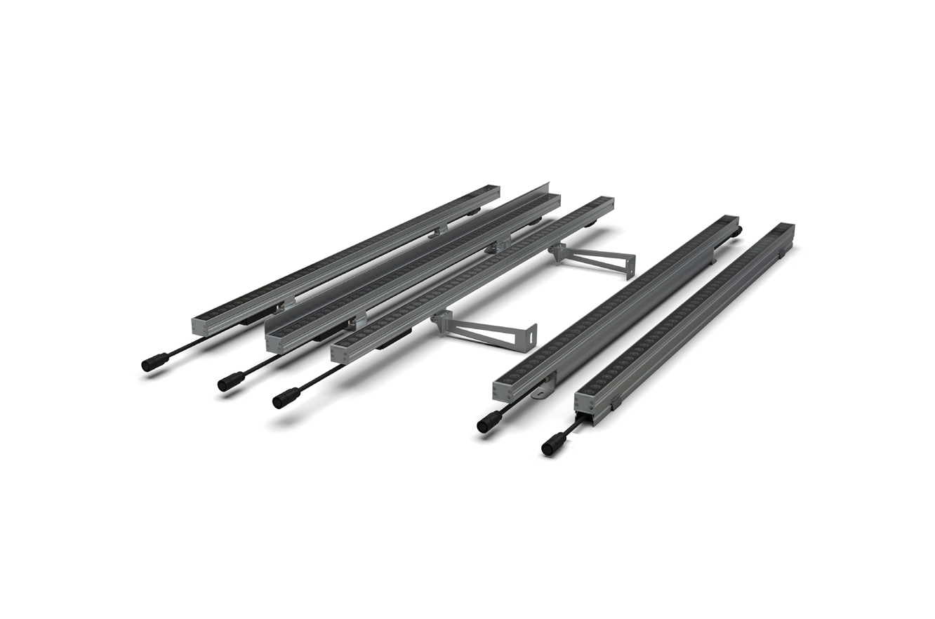
Compact 30 mm Profile: The LLS-OP-W30C low-profile linear lightbar, featuring an engineered flat aluminum mounting clip that fits within strict 1.25-inch curtain-wall pockets.
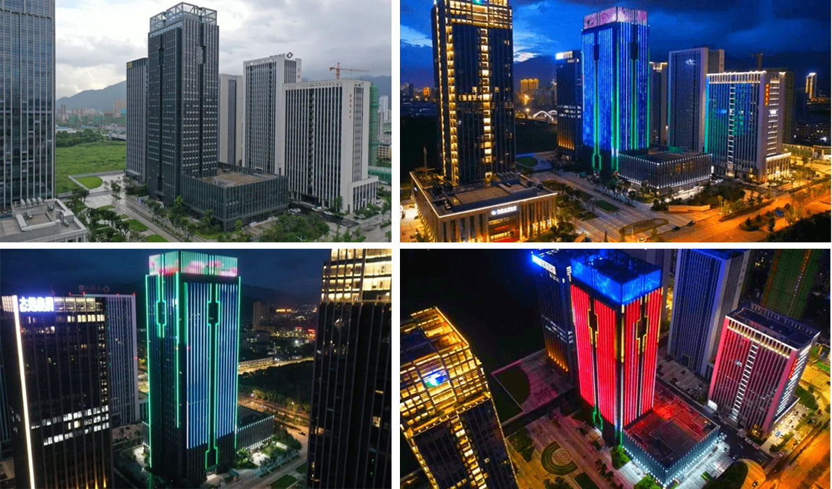
Shallow Slab Integration: Over 3,000 linear bars concealed in customized shallow floor channels at Linhai Business Headquarters, demonstrating flush glare-free architectural integration.
| Parameter | Live! Maryland Project Spec | Catalog Standard LLS-OP-W30B/C |
|---|---|---|
| Cavity Depth Limit | 1.25 in (31.75 to 32.0 mm) | Recommended >40 mm reveal |
| Luminaire Body + Clip | 30 mm body + flat countersunk clip | 30 mm body + standard clip (35 mm) |
| Length Increments | Custom 1,219 mm / 610 mm / 305 mm | Standard 1,220 mm / 1,000 mm / 500 mm |
| Power per Unit | 15W RGB (Calibrated for 24V line drop) | 18W RGB / 21W RGBW |
| Lens Material | Tempered Optical Glass | Glass (W30C) or Polycarbonate (W30B) |
| Third-Party Listing | ETL Listed (UL 2108 / UL 1598) | ETL (W30C) / CE Compliant |
3.3 Case Study 2: Linhai Business Headquarters — Shallow Floor-Slab Integration
While Live! Maryland represents a horizontal slab-edge curtain-wall constraint, the Linhai Business Headquarters Project (Taizhou, Zhejiang, 62,969 m² commercial complex) illustrates a distinct structural challenge.
- The Structural Constraint: The architectural design called for continuous linear grazing along the base of extensive glass curtain-wall facades. However, the structural concrete floor slabs behind the curtain wall were extremely shallow, preventing the excavation or casting of standard deep recessed in-ground fixture troughs.
- The Engineering Solution: Over 3,000 linear lightbars (based on the LLS-OP-W30B platform, 21W, 15°×55° asymmetric optics) were integrated into specially fabricated low-profile floor channels. Custom-engineered polycarbonate lenses were fabricated to lay flush with the shallow channel edge.
- The Engineering Result: The flush assembly completely concealed the LED light sources from pedestrians and office occupants, while the robust IP67 seal protected internal components from floor cleaning moisture, rain runoff, and construction debris. The linear bars operated under synchronized DMX512 control alongside architectural spotlights (SP-DKP-F170, 40W, 15°) and wall washers (LWW-WZB-W55, 36P, 4000K).
3.4 Tool Access and Replacement at Height
An installation is not complete if a fixture can be snapped into a cavity but cannot be uninstalled for maintenance.
- Tool Clearance: Snap-in spring clips require vertical clearance above the cavity opening to disengage. In a 32 mm cavity, spring clips often cannot flex. Flat aluminum clips with lateral sliding screws or end-cap release pins must be specified.
- Cable Exit Clearance: Standard waterproof IP68 cable glands require a straight entry length before the cable can bend. In shallow reveals, luminaires should feature rear-exit or bottom-exit recessed cable entries rather than end-cap glands to prevent cable pinching against curtain-wall mullions.
3.5 Chapter Output: The Curtain-Wall Installation Submittal
To verify installation feasibility, the contractor must submit:
- A 1:1 scale composite cross-section drawing showing the luminaire, mounting clip, fastener head, and cable bend seated within the architect's specific curtain-wall extrusion;
- Proof of tool access demonstrating how a technician can unfasten and remove a single damaged luminaire without dismantling adjacent curtain-wall panels;
- Calculated weep hole and thermal expansion gaps preventing water entrapment and structural binding.
4. Coordinate Power, Branching and Addressing
Fitting luminaires into a curtain-wall cavity is only half the engineering task. How electrical power and digital control signals reach those luminaires through sealed building envelopes determines the system's long-term reliability.
4.1 Fixed Penetration Points and Low-Voltage Drop
On modern insulated curtain-wall towers, penetrations through the building envelope are strictly limited. Each penetration requires specialized EPDM gaskets, structural silicone seals, and MEP coordination. Punching additional field holes after facade installation is completed is prohibited.
In a 24V DC constant-voltage LED system, long branch runs encounter voltage drop (Vdrop = 2 × I × L × R / 1000). When operating voltage at the end of a run drops below the driver's regulated minimum operating threshold, LED drivers begin to drop out of regulation, producing visible color shift, flicker, and reduced luminous output.
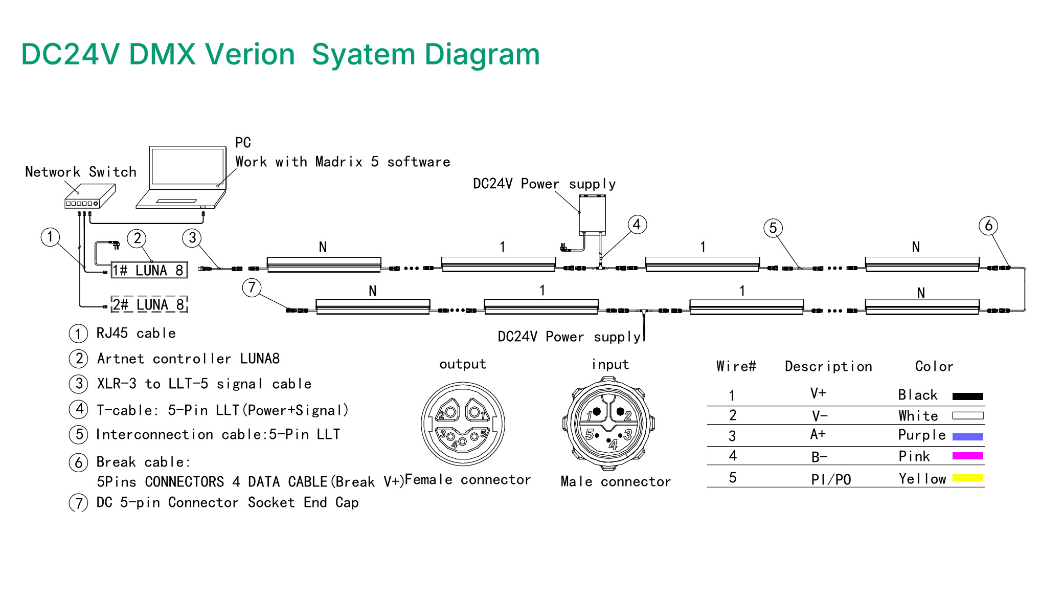
Wiring Schematic — DC24V DMX System: Signal from the network switch and LUNA8 controller and power from the 24V supplies both travel through 5-pin LLT T-cable splitters, so the fixtures on each row are fed from the middle of the run instead of from one end.
4.2 The T-Type Power Architecture: Capabilities and Limits
To resolve this on Live! Maryland—where 10-fixture rows were common—a T-Type Power Distribution Architecture was deployed:
- A single penetration feeds into an external weather-sealed T-splitter.
- The splitter divides the incoming 24V DC feed into two outgoing branch legs running in opposite directions.
- Each branch powers a maximum of five L12 (1,219 mm, 15W) fixtures.
- The Engineering Math: Five 15W fixtures draw 75W total. At 24V DC, the branch current is I = 75W / 24V = 3.125A. For 14 AWG (2.08 mm²) copper conductors carrying 3.125A across a 6.1-meter branch run, the calculated line drop is approximately 0.8V DC (~3.3%), maintaining operating voltage comfortably within driver regulation limits.
4.3 High-Rise DMX Addressing: Sequential Coders vs. RDM Prerequisites
Multi-floor high-rise addressing presents substantial operational risk. Once luminaires are installed at heights of 50 to 150 meters within narrow curtain-wall reveals, dismounting a unit to reset hardware DIP switches or re-address an incorrectly commissioned bar requires specialized rope-access teams and suspended scaffolding.
- If NO: Deploy handheld offline sequential address coder (C-Mode) prior to or during snap-in installation.
- If YES: Proceed to Criterion 2.
Criterion 2: Has the transmission bus impedance (120Ω) and reflection noise isolation been certified end-to-end on site?
- If YES: Ground-level remote RDM discovery and addressing is authorized.
- If NO: Revert to handheld offline sequential programmer for maximum commissioning reliability.
- Offline Sequential Address Coders (The High-Reliability Method): As implemented on Live! Maryland, each luminaire utilizes an intelligent onboard MCU supporting continuous sequential addressing (C-Mode). Using a dedicated handheld programmer, technicians connect fixtures in sequential bench order prior to or during snap-in installation. Bar 1 automatically programs channels 1–12; Bar 2 takes 13–24; Bar 3 takes 25–36. Addresses are locked in non-volatile EEPROM, eliminating field-addressing errors at height.
- Remote Device Management (RDM / ANSI E1.20) Prerequisites: While RDM enables remote ground-level addressing over the DMX data pair, it introduces strict system requirements:
- Every DMX opto-splitter and line amplifier between the console and the luminaire must support bidirectional RDM communication.
- The transmission line must maintain clean 120Ω impedance, proper shield grounding, and correct bus termination. Reflected pulses on branch lines can corrupt RDM discovery packets.
- If the electrical contractor installs conventional unidirectional DMX splitters, remote RDM discovery will fail completely.
- Maintenance Replacement Workflow: When a damaged luminaire is replaced during future maintenance, the replacement unit must be pre-addressed using the handheld coder to match the failed bar's channel block before being installed in the wall cavity. For comprehensive DMX bus wiring, termination resistance, and opto-isolation rules, refer to our DMX Fixture On-Site Commissioning Guide.
5. Validate the Mockup and Nighttime Operating Scenes
Computer lighting simulations in DIALux evo or AGi32 provide necessary baseline calculations, but they cannot simulate real-world curtain-wall assembly tolerances, micro-variations in Low-E glass specular reflectance, or the light-trapping behavior of interior window blinds. The design intent must be validated through a physical 1:1 On-Site Mockup.
5.1 Clear Separation: Exterior Compliance vs. Interior Experience
A frequent error during mockup reviews is conflating exterior environmental compliance with interior subjective comfort:
- Location: Measured on the EXTERIOR surface of the vision glass.
- Target: Vertical Illuminance (Ev in lux) against pre/post-curfew zone limits.
- Tool: Calibrated illuminance meter held flush against outer glass plane.
DOMAIN 2: Interior Guest Comfort & Visual Experience (Operator Brand Standards)
- Location: Evaluated from INSIDE the guest room (at seated and pillow height).
- Target: Direct line-of-sight view into bare LEDs; stray light bleeding past sheer drapes or blackout curtain perimeter tracks.
- Tool: Qualitative visual audit + interior photopic luminance check.
5.2 Selecting Representative Mockup Locations
A mockup installed on a low-level solid boundary wall provides no useful data regarding guest-room window spill. An effective mockup must be located on the actual building envelope and satisfy three criteria:
- Vertical Transition: Cover adjacent vertical floors, spanning the slab edge, vision glass below, spandrel panel, and vision glass above.
- Corner and Balcony Geometry: If the building incorporates recessed corner balconies or projecting mullion fins, the mockup must include at least one transition zone to evaluate secondary specular bounce.
- Active Glazing: The mockup must be installed against actual production Low-E glass units, not temporary plywood or uninsulated test glass.
5.3 Operating Scene Calibration
A hotel facade lighting system must not operate at 100% output continuously throughout the night. Operating requirements change drastically between peak evening arrival hours and late-night sleeping hours.
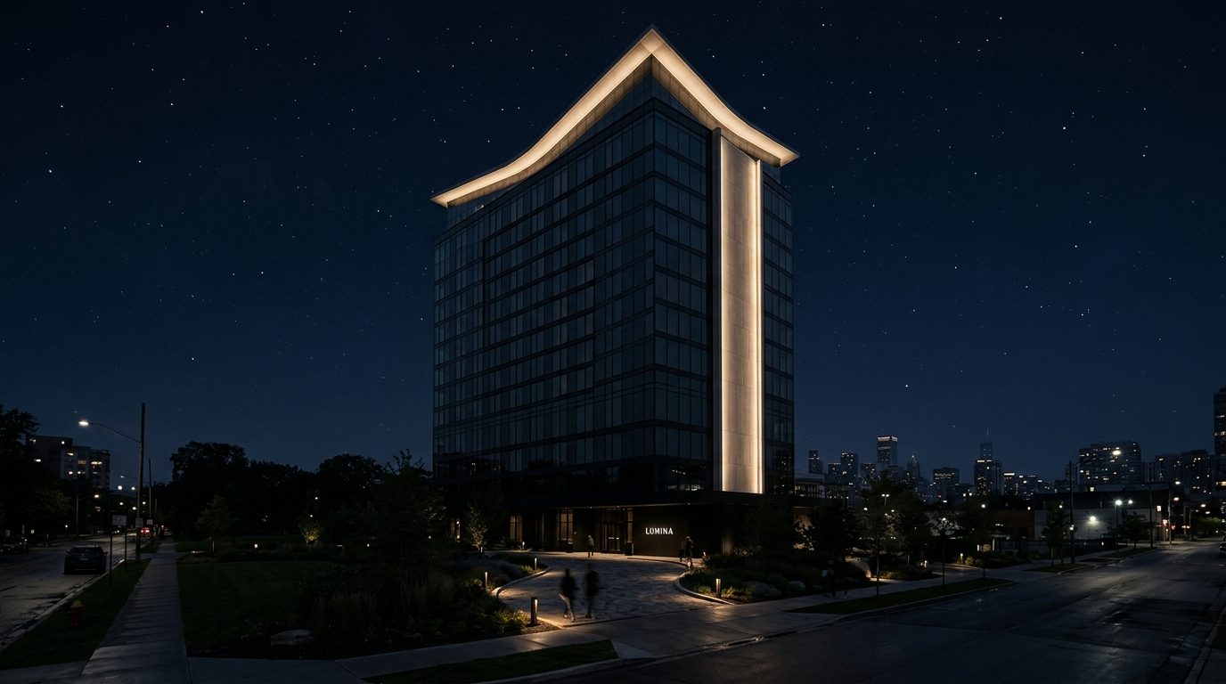
Late-Night Curfew Mode (>23:00): The guest-room facade is peaceful and dark, ensuring complete sleep comfort for guests with zero upward light spill, accentuated only by a faint, delicate warm graze on the crown and vertical shear wall plus low-level pathway bollards.
- Peak Evening / Welcome Scene (Dusk to 22:00/23:00): The facade operates at full designed contrast. Slab-edge linear fixtures trace floor plates; vertical washers define structural corners; entrance spots warmly highlight the porte-cochère. Direct spill onto guest glazing is constrained by optical cutoff, allowing normal guest activity.
- Curfew / Sleep Scene (22:00/23:00 to 06:00): Control systems transition the facade into a low-impact mode. Luminaires mounted directly adjacent to guest-room windows are dimmed or powered off entirely. Illumination is concentrated exclusively on non-habitable architectural surfaces: the tower crown, solid shear-wall elevator cores, and low-level ground pathways.
- Maintenance / Service Scene: Static warm-white burn-in mode for facade maintenance, window-washing cradles, and fixture inspection.
5.4 Modifying Parameters and Final Sign-Off
If the initial mockup reveals interior spill exceeding project targets, the project team must adjust parameters in a disciplined sequence:
- First, adjust the mechanical tilt angle outward by small increments (e.g., 2° to 5°) to sharpen the spandrel cutoff;
- Second, verify whether installing an internal honeycomb louvre eliminates peripheral flare;
- Third, reduce control scene output levels on glazing-adjacent circuits.
Any modification to optical lenses, shielding accessories, or mounting angles requires re-testing all three interior blind conditions before signing the final submittal approval.
6. Specify the Approved Configuration and Supporting Documents
Once the optical selection, curtain-wall assembly details, electrical distribution, and mockup performance have been validated, the conclusions must be codified into a formal technical specification. Broad, generic catalog references must be eliminated to prevent delivery discrepancies.
6.1 The Technical Submittal Package Breakdown
A complete technical submittal package must contain six mandatory documents:
- Exact Part Number Nomenclature: Broad series codes invite contractor substitution. The submittal must specify every attribute: profile model, length code, wattage, LED color/CCT, input voltage, control protocol, beam angle code, front lens material, and certification listing (e.g., LLS-OP-W30C-L12-15W-RGB-24V-DMX-F1555-GL-ETL).
- Matching Photometric Package: IES files must reflect the exact production configuration. An IES file measured without an internal louvre is invalid if an internal louvre is specified on site.
- Assembly Shop Drawing: Fully dimensioned 2D CAD cross-section showing engagement within the actual curtain-wall extrusion profile, tool clearance for screw fastening, cable bend radius, and weep hole drainage paths.
- Electrical Load and Voltage Drop Schedule: Engineering calculations proving that the furthest luminaire on any 24V DC branch circuit receives a minimum of 22.8V DC under full 100% white burn-in load.
- Accredited Certification Reports: Regional code requirements determine testing standards. For US commercial projects under the NEC, submittals must provide official ETL listing documentation confirming testing to UL 1598 or UL 2108. For European, Asian, or Middle Eastern projects, corresponding CE, CB, or UKCA reports apply.
- Signed Mockup Sign-Off Protocol: Field measurement report signed by the lighting consultant, facade contractor, and owner's representative.
6.2 Managing Spare Parts and Future Replenishment
High-rise hotel facades require long-term maintenance planning. When ordering project spares or future replacement units:
- Color Consistency Specification: Verify manufacturer chromaticity binning standards (typically requesting 3-step MacAdam ellipse, SDCM ≤ 3) to maintain color consistency across initial orders and future maintenance batches.
- Pre-Addressed Spares: Replacement bars must be ordered with pre-configured DMX addresses or programmed using the handheld coder prior to high-altitude installation.
6.3 Supporting Luminaires & High-Power Wall Washers
While low-profile linear lightbars (LLS-OP-W30B / W30C) handle horizontal slab-edge glazing borders, architectural crowns and non-habitable shear wall towers require high-power vertical projectors:
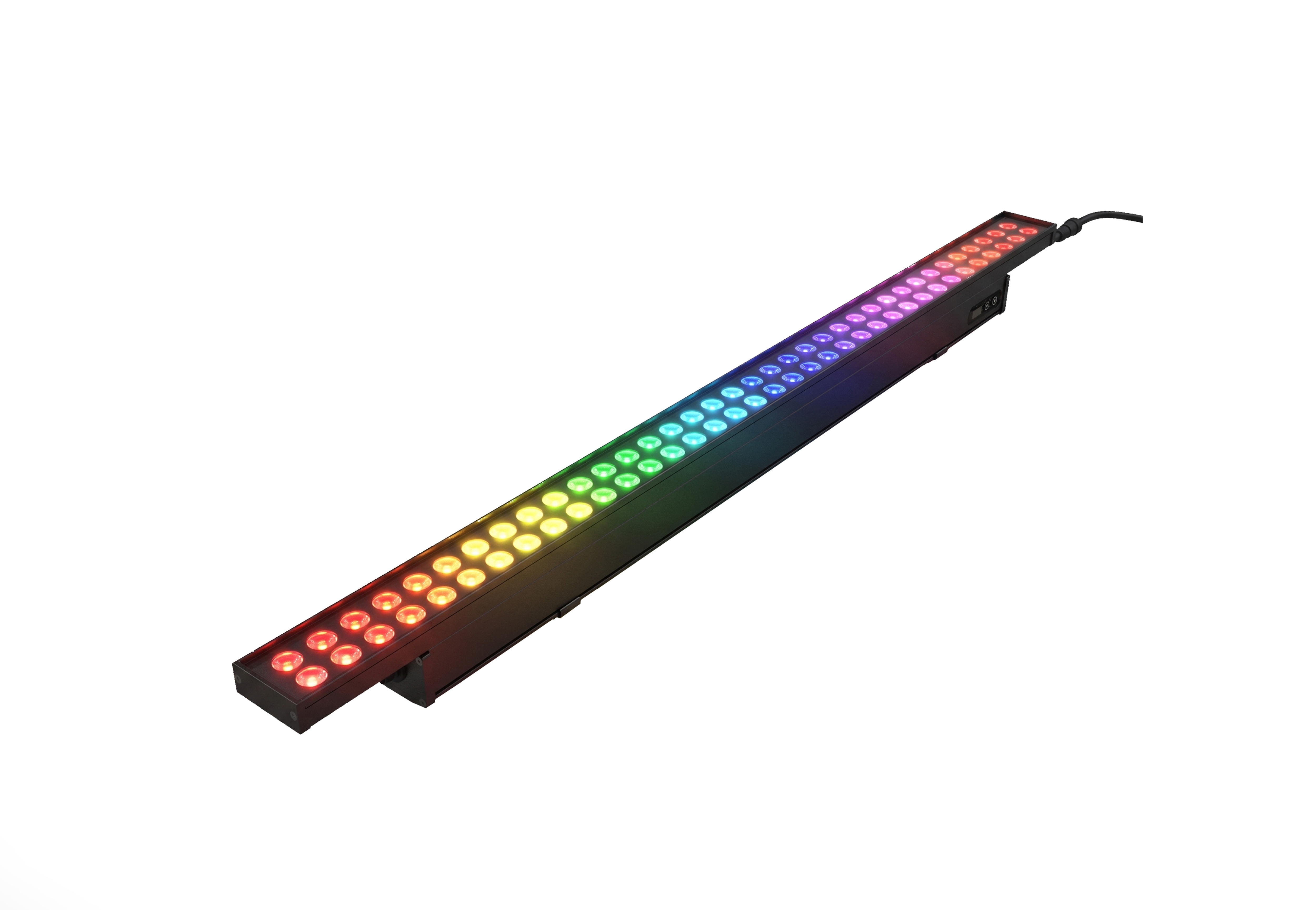
High-Efficiency Vertical Grazing: The LWW-OP-W75 wall washer provides intense narrow-beam vertical grazing for solid elevator shear walls and crown structures.
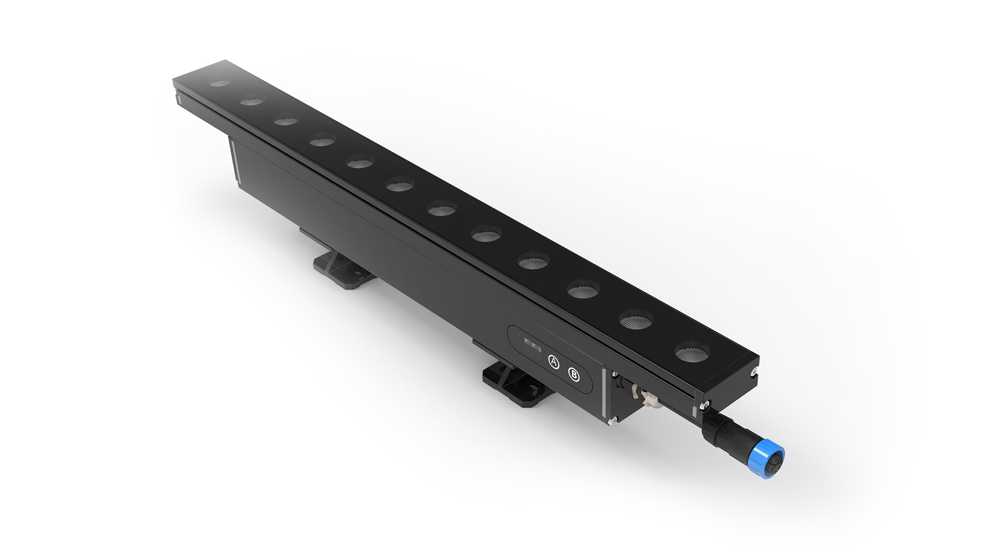
Long-Throw Architectural Washing: The LWW-WZB-W55 luminaire engineered for architectural facade surfaces with robust IP67 mechanical shielding.
Technical Submittal & Verification Checklist
| Project Phase | Submittal Item | Mandatory Technical Requirement | Common Engineering Trap | Verification Method | Responsible Party |
|---|---|---|---|---|---|
| Schematic Design | Facade Zoning | Clear separation between Tower (Layer 1), Arrival (Layer 2), and Grounds (Layer 3). | Specifying ground landscape fixtures on the tower brief, or over-washing arrival canopies. | Architectural zoning schedule review. | Lighting Designer |
| Schematic Design | Glazing Mapping | Vision glass and operable windows delineated as unlit zones. | Assuming the entire facade is a continuous solid projection surface. | Elevation drawing audit marking unlit window envelopes. | Facade Engineer / LD |
| Design Development | Optical Selection | Full IES/LDT polar curve evaluated at actual mounting tilt; verification of cutoff angle. | Believing a "15°" nominal beam angle guarantees zero high-angle spill light. | Photometric calculation of vertical lux (Ev) on exterior glass. | Lighting Consultant |
| Design Development | Spill Light Limits | Establishing pre-curfew and post-curfew limits based on CIE 150 environmental zones (E1–E4). | Relying on unverified slogans like "zero light trespass". | Calculation grid on exterior face of vision glass in DIALux. | Lighting Consultant |
| Detail Engineering | Cavity Assembly | Total assembly height (Hhousing + Hbracket + Hscrew) must sit within cavity depth with countersunk screws. | Specifying a 30 mm fixture into a 32 mm cavity with pan-head screws that cause dimensional interference. | 1:1 scale composite section CAD drawing. | Facade Contractor / Mfr |
| Detail Engineering | Power Distribution | Low-voltage 24V DC branch voltage drop maintained <5%; T-type branching where penetrations are fixed. | Stringing excessive fixtures in-line, causing visible color shift and dimming at run ends. | Electrical circuit load and conductor length schedule. | MEP Consultant / Mfr |
| Detail Engineering | Code Compliance | Appropriate listing (NRTL/ETL for US NEC installations; CE/CB for applicable international jurisdictions). | Submitting CE-only marked fixtures on a US commercial building project. | Verification of active directory listing on accredited agency portals. | General Contractor |
| Procurement / Pre-Con | Addressing Architecture | Sequential addressing via handheld programmers or fully certified end-to-end RDM topology. | Relying on RDM when intermediate splitters or controllers do not support bidirectional RDM. | Control schematic review and factory pre-addressing schedule. | Systems Integrator |
| Pre-Installation | 1:1 On-Site Mockup | Physical mockup across adjacent floors verifying exterior cutoff (Ev) and interior blind bleed under peak/curfew. | Skipping mockup and discovering interior window glare after full tower procurement. | Calibrated field lux meter on exterior glass + interior qualitative inspection. | Owner / LD / Contractor |
Frequently Asked Questions
How do you prevent light from entering guest-room windows when grazing hotel facades?
Preventing window spill requires a multi-layered approach: selecting asymmetric optical lenses (such as 15°×55°) with steep rear cutoffs, installing factory internal honeycomb louvres to absorb high-angle peripheral flare, maintaining physical mounting setback from the vision glass, and scheduling automated curfew scene dimming during sleeping hours.
Can a 30 mm luminaire fit into a 32 mm curtain-wall reveal?
Only if the mounting hardware and fasteners are engineered for flush integration. Standard mounting clips and pan-head screws add 3 to 5 mm to the vertical stack, causing physical interference. To fit within a 32 mm reveal, luminaires must utilize low-profile aluminum clips with countersunk screw recesses and recessed cable exits.
Why is 24V DC preferred over 48V or line voltage for curtain-wall linear bars?
24V DC constant-voltage systems provide Class 2 low-voltage safety compliance, simplifying building code approval under US NEC and international standards without requiring bulky conduit inside sealed curtain-wall cavities. When combined with T-type branching architectures, voltage drop is safely constrained below 5%.
Is RDM always recommended for high-rise facade DMX addressing?
RDM is highly efficient only when every intermediate opto-splitter, line amplifier, and controller supports bidirectional ANSI E1.20 communication, and cable bus impedance is certified. On installations with mixed hardware, handheld offline sequential address coders (C-Mode) offer significantly higher commissioning reliability without network packet corruption risks.