


Long-Distance DMX for Bridge and Linear Lighting: Architecture, Transport Options and Commissioning
Field-proven DMX512 transmission technologies for complex bridge environments — from 3 km spans to remote dead zones.
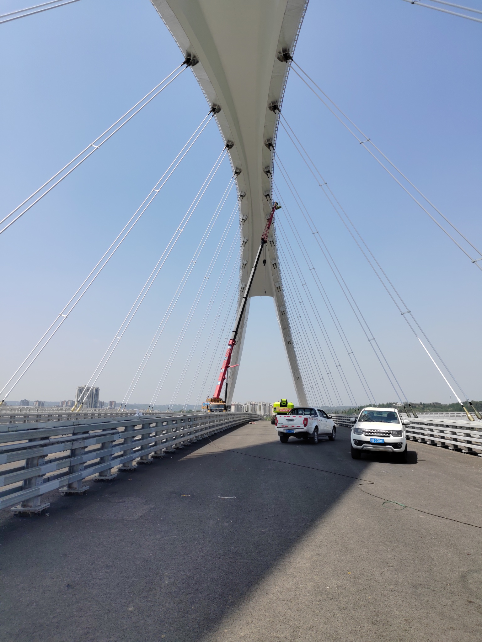
For bridge lighting, riverfronts, elevated roads, and large façade projects, the question is not simply how far a DMX signal can travel. The design question is where the DMX link should end, how the long-distance transport layer should be built, and what the system should do when part of that transport layer is unavailable.
This article outlines a practical way to design that control path without relying on unsupported performance claims.
Start by Separating Three Distances
“Long-distance DMX” can refer to three different things:
- The length of one physical DMX data link between a controller, splitter, or gateway and its fixtures.
- The distance from a central control room to a remote control cabinet or field node.
- The total physical extent of the lighting project.
These are not the same design problem.
A local DMX branch should remain a controlled electrical data link. The long connection between a control room and a remote cabinet may instead use fibre, Ethernet, a licensed or unlicensed point-to-point radio link, or a managed cellular connection. A project can span several kilometres while each local DMX branch remains comparatively short and testable.
Build a Healthy Local DMX Branch First
Long-distance transport cannot compensate for poor DMX wiring at the fixture level.
DMX512 is a serial control protocol. A single universe provides up to 512 data slots, with slot 0 reserved as the start code and slots 1 through 512 available as data slots. Fixture count therefore depends on the DMX channel footprint of each fixture, not on fixture quantity alone. For example, a 12-channel RGBW fixture uses 12 slots; a universe with no other allocation can theoretically address up to 42 such fixtures, subject to the controller and system design.
For each local branch, verify the following before extending the system over a longer transport network:
- Use data cable with suitable characteristic impedance, commonly 120 Ω cable intended for DMX or EIA-485 use.
- Wire fixtures in a daisy-chain or bus topology. Do not create uncontrolled Y branches or star connections from a DMX output.
- Fit the required termination at the end of the data link. ANSI E1.11 specifies a 120 Ω termination between Data+ and Data− to reduce reflections that can cause equipment malfunction.
- Keep the data path, fixture addressing, connector pinout, shield treatment, and controller configuration documented.
- Consider isolated splitters where branches, separate power zones, or ground-potential differences make a single continuous link unsuitable.
- Treat power quality, surge protection, enclosure sealing, and connector strain relief as part of control reliability rather than as separate installation details.
A system that flickers or loses devices on a 50 m bench test will not become reliable after a radio, fibre, or cellular link is added. Stabilize the local branch first.
Why Direct Cable Runs Become Difficult
A long physical cable route can be practical when there is a protected path, accessible pull boxes, controlled grounding, and a maintainable cable route. It becomes less attractive when the route crosses water, traffic lanes, expansion joints, rail corridors, or areas where later cable access will be expensive.
The most common field issues are not mysterious protocol failures. They are usually one or more of the following:
- A branch was added to a daisy-chain without a splitter.
- The end of a DMX line was left unterminated.
- Data cable was substituted with unsuitable cable during installation.
- Fixtures on separate electrical zones developed a ground-reference problem.
- A cabinet lost power, while the central controller continued transmitting.
- A radio path was obstructed by a bridge element, vegetation, vehicle traffic, or later construction.
- A remote network device restarted but did not restore its expected configuration.
- A cellular router remained online but changed network conditions, SIM status, or VPN availability prevented access to the control network.
These failure modes should shape the architecture from the beginning.
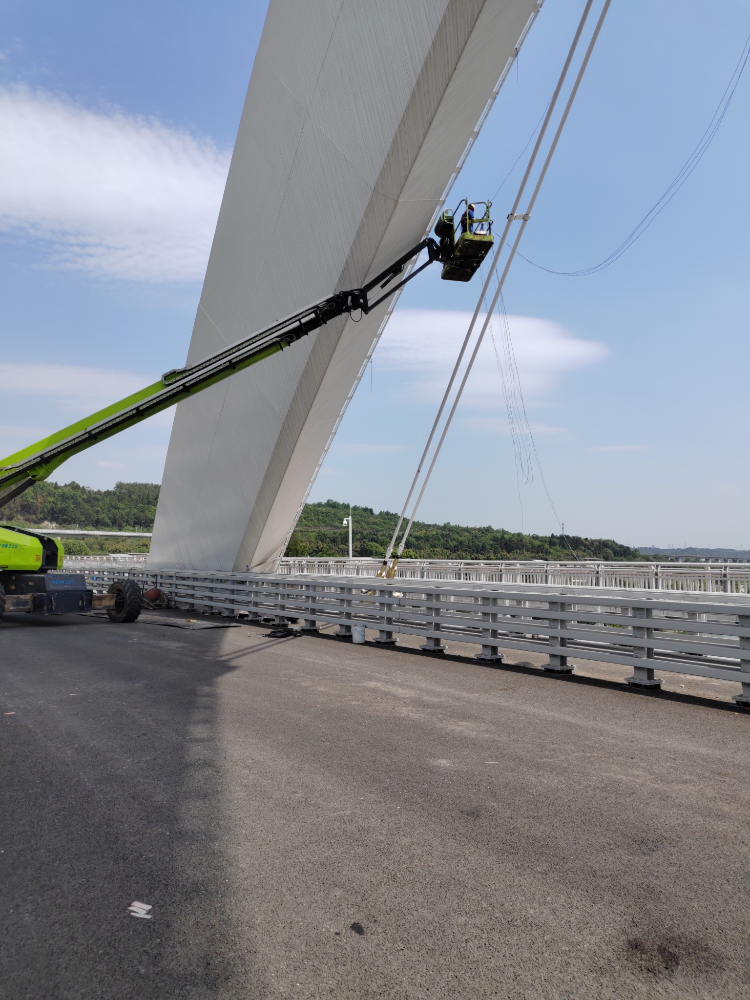
Signal attenuation and interference grow with span length and environmental complexity.
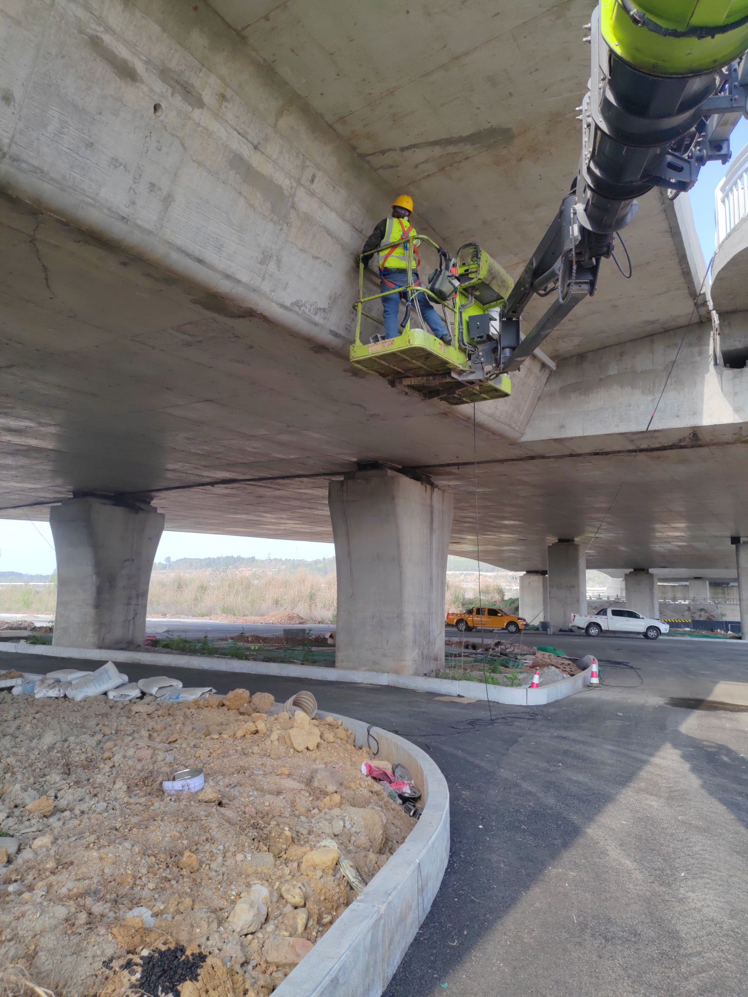
Bridge traffic and high-voltage lines generate interference that can distort DMX frames.
Use a Layered Control Architecture
For distributed outdoor lighting, the clearest architecture separates the system into four layers:
| Layer | Main function | Typical equipment |
|---|---|---|
| Control layer | Stores schedules, scenes, triggers, and operator access | Lighting controller, show-control server, BMS interface |
| Transport layer | Carries control data across the long route | Fibre network, Ethernet switch, point-to-point radio, managed cellular router |
| Field-node layer | Converts the transport signal into local control branches | Ethernet-to-DMX gateway, DMX/RDM node, isolated splitter |
| Fixture layer | Receives DMX data and produces the lighting output | LED fixtures, drivers, decoders, local termination |
This approach prevents a single DMX cable from being asked to serve as the control-room backbone for an entire bridge or waterfront. It also makes faults easier to isolate: the control room, transport path, remote node, and fixture branch can be tested separately.
Choosing the Long-Distance Transport Layer
The selection should be based on physical route, access, required availability, latency tolerance, maintenance resources, and cybersecurity requirements—not on a generic claim that one technology is “best.”
| Transport method | Usually suitable when | Main design concerns | Avoid relying on it when |
|---|---|---|---|
| Fibre | A permanent route is available and high electrical isolation is valuable | Route protection, splice quality, switch power, cabinet environment, redundancy | Civil work is impossible or the cable route cannot be maintained |
| Wired Ethernet over existing infrastructure | Managed Ethernet already reaches each field cabinet | Network ownership, VLAN design, PoE/power budget, switch configuration, cybersecurity | The network is unmanaged, shared without controls, or unavailable during project operation |
| Point-to-point wireless bridge | There is a verified line of sight between fixed endpoints and cable crossing is difficult | Fresnel-zone clearance, mounting rigidity, weather exposure, antenna alignment, interference, surge protection | The path is obstructed, endpoints move, or maintenance access is poor |
| Managed cellular connection | A remote cabinet needs monitoring, scheduled updates, or a fallback communications path | Carrier coverage, SIM management, VPN, data plan, router health, remote access policy | The project requires deterministic local show timing over a public network |
| Direct extended DMX cabling | The route is short, protected, accessible, and electrically controlled | Cable impedance, termination, topology, EMI, grounding, surge exposure | The cable crosses difficult civil zones or becomes too costly to inspect and repair |
For dynamic architectural scenes, the most robust pattern is often to keep real-time playback or scene logic local to the project controller and use the wide-area connection for supervision, updates, diagnostics, or higher-level commands. The acceptable design depends on the effect type, the controller capabilities, and the consequences of a communications interruption.
Fibre for Permanent, High-Exposure Routes
Fibre is often the preferred backbone where a permanent civil route exists, particularly across long linear structures or between electrically separated cabinets. It provides electrical isolation between network segments and avoids many of the ground-reference issues associated with long copper data routes.
A typical arrangement is:
Control room → managed Ethernet switch → fibre backbone → remote cabinet switch → Ethernet-to-DMX gateway → isolated DMX splitter → local fixture branches
The design still requires field discipline. The fibre link must be protected from mechanical damage; active switches and gateways need reliable cabinet power; and the remote DMX output must be commissioned as carefully as a local controller output.
Fibre does not eliminate the need for termination, correct DMX topology, fixture addressing, or local surge protection. It simply moves the long-distance part of the system from a copper DMX link to a network backbone.
Wireless Point-to-Point Links Need a Site Survey
A fixed wireless bridge can be useful where trenching or bridge crossing is impractical. It should not be selected from a map alone.
Before finalizing a radio path, confirm:
- Clear line of sight between antennas.
- Adequate Fresnel-zone clearance, not just visible end-to-end alignment.
- A mounting structure that will not change antenna alignment under wind, vibration, or thermal movement.
- Local power and surge protection for both radio endpoints.
- Cabinet ventilation and environmental protection appropriate to the site.
- A documented channel plan and interference assessment where spectrum congestion is possible.
- A recovery procedure if a radio, switch, or gateway restarts after a power event.
The radio link should be accepted through site testing at the final mounting height and orientation. A successful temporary ground-level test is not enough.
Cellular Is Better Treated as a Managed Backhaul or Backup Path
Cellular connectivity can be useful for remote sites where no owned network or fibre route is available. It is often well suited to remote monitoring, schedule updates, controller support, alarms, and access through a secure VPN.
It should not automatically be treated as the primary path for time-critical frame-by-frame lighting playback. Performance depends on local coverage, carrier routing, signal conditions, router configuration, and the operational status of the SIM and data plan.
Where cellular is used, document the following:
- Carrier and coverage test results at the installed cabinet location.
- SIM ownership and renewal responsibility.
- APN, VPN, firewall, and remote-access configuration.
- What the lighting system does during a network outage.
- How the system recovers after service restoration.
- Who receives an alert if the router or controller is unreachable.
A controlled fallback scene is usually more valuable than a claim of uninterrupted connectivity.
Design for Loss of Communication
Every distributed lighting project should define its behaviour when communication is lost.
For each remote cabinet or control zone, specify:
- The last valid scene or fallback scene the fixtures should hold.
- Whether the controller continues to run a local schedule without the central network.
- Whether fixtures restart in a safe state after power restoration.
- Whether a remote gateway returns to the correct addressing and output state after reboot.
- Whether alarms are generated for loss of controller, network, power, or DMX output.
- Who can access the system locally if remote access is unavailable.
These decisions belong in the control narrative and commissioning plan, not only in the installer’s troubleshooting notes.
Commission Each Layer Separately
Commissioning should proceed from the local link outward:
- Verify fixture power, addressing, and operation from a local DMX test source.
- Verify each DMX branch, including termination, polarity, splitter outputs, and fixture response.
- Verify the field gateway or node converts network data to the expected DMX universe and address range.
- Verify the fibre, wired Ethernet, radio, or cellular transport path independently.
- Test control recovery after power cycling the remote cabinet, network switch, gateway, and controller.
- Test the defined fallback condition by intentionally disconnecting the long-distance transport layer.
- Save configuration files, addressing tables, network diagrams, cabinet photographs, and final test records as part of handover.
This process prevents a common commissioning mistake: treating the full system as one black box and trying to diagnose a remote fault from the control room.
For fault isolation procedures on live DMX runs, see our guide to on-site DMX commissioning and troubleshooting.
Information to Confirm Before Procurement
Before selecting the control architecture, collect the following project information:
- Site plan showing every cabinet, fixture group, cable route, and physical obstruction.
- Number of fixtures, DMX channel count per fixture, and required universe allocation.
- Required scenes, playback type, schedules, and acceptable response behaviour.
- Available power and communications infrastructure at every field cabinet.
- Distance and accessibility of proposed cable or radio paths.
- Environmental conditions, including salt spray, vibration, temperature range, lightning exposure, and enclosure requirements.
- Whether local staff can access remote cabinets after handover.
- Required cybersecurity, VPN, account ownership, and remote-support rules.
- Required fallback scene and restart behaviour.
A long-distance DMX project becomes manageable when the long route is treated as a transport design problem and the local DMX branches are kept electrically disciplined. The goal is not to make one signal travel as far as possible. The goal is to make each part of the control path testable, recoverable, and maintainable.
FAQ
Can DMX be run directly over a long bridge?
It can be used over a direct cable route where the link is correctly designed, protected, terminated, and maintainable. For long or difficult routes, it is usually better to place field nodes along the structure and use fibre, managed Ethernet, or a properly surveyed wireless bridge for the backbone. The local fixture branches can then remain short DMX links.
Does a wireless bridge replace DMX wiring to the fixtures?
No. A wireless bridge usually replaces the long-distance transport between two network points. A remote gateway or controller still needs correctly wired local DMX branches to reach the fixtures.
Is 4G or 5G suitable for dynamic lighting control?
It can be useful for monitoring, support, schedule updates, and selected control applications, but suitability for dynamic real-time effects depends on the controller design and the consequences of variable public-network performance. Define local fallback behaviour rather than assuming continuous service.