


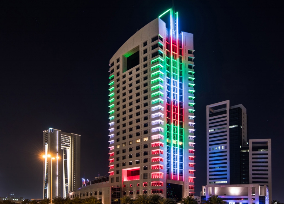
Philips UniBar BCS342 Alternative: Evaluating TPK LLS-OP-D50
A technical guide to optical performance, installation, power, control, certification and proven project applications — for new builds and retrofit evaluation. Philips and UniBar are trademarks of Signify Holding. TPK Lighting is an independent manufacturer. This page is a factual selection guide based on publicly available specifications; it is not affiliated with or endorsed by Signify.
When Is the D50 Worth Evaluating?
The relevant comparison is not simply whether both products are linear luminaires, but whether the selected D50 configuration meets the project’s optical, mechanical, electrical and control requirements.
If your project specification references Philips UniBar BCS342, TPK LLS-OP-D50 is an alternative worth evaluating for outdoor direct-view architectural lighting. This guide separates new-project selection from existing-system replacement, and explains the technical information needed for each.
Building outlines
Continuous linear accents and façade emphasis → proceed with the evaluation below.
Segmented pixel effects
Specified pixel animations → check the pixel and channel configuration first (design features, control).
Reusing existing hardware
Keeping brackets, power supplies or connectors → verify interfaces and mounting dimensions first (checklist).
Special environments
Extreme temperatures or special conditions → review the specific version against project requirements.
Define the Reference Model Before Comparing
One rule applies before anything else: both reference codes, or nothing.
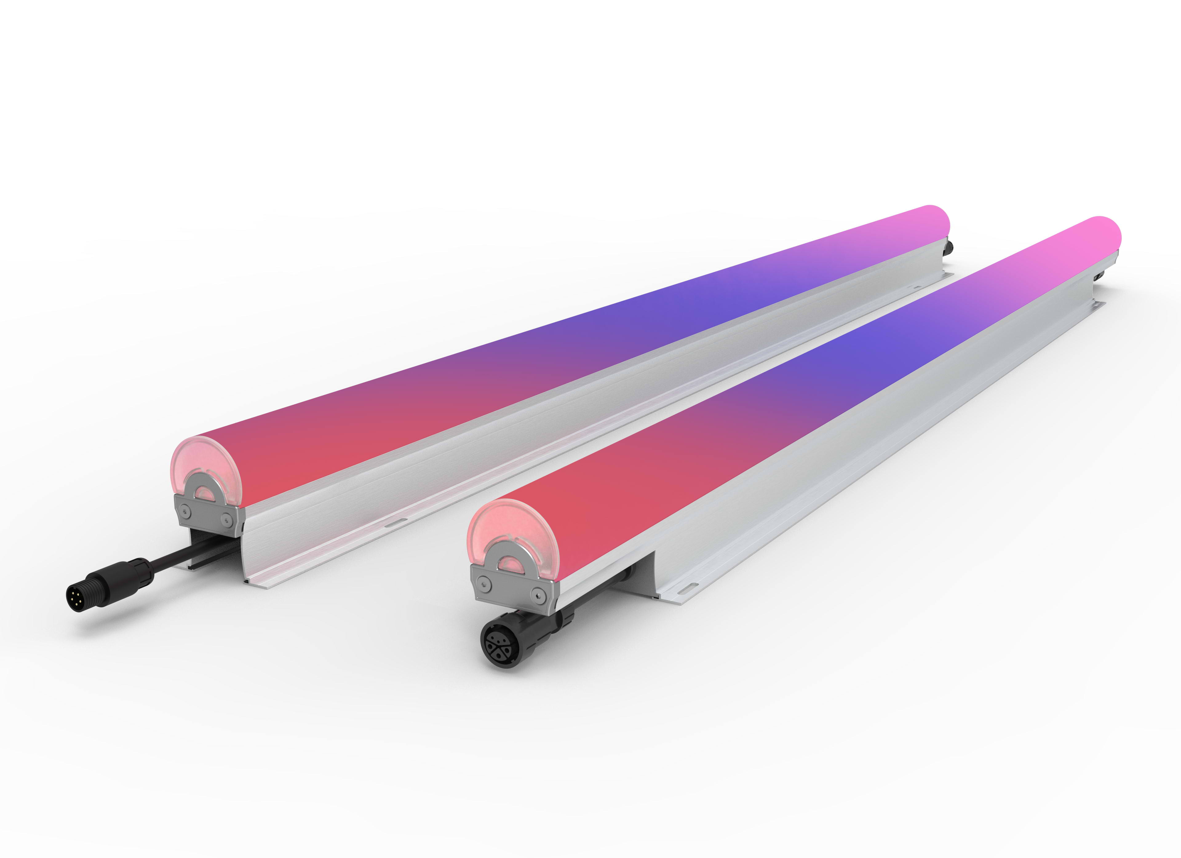
“BCS342” is a product family, not a single configuration
Philips offers it in multiple lengths (L30 / L50 / L100), colors (white, RGB, RGBW/RGBNW) and control options, including 10-pixel DMX versions. Before any meaningful comparison, match a specific D50 configuration: length, input voltage (24V DC or 100–277V AC), color and control version.
Full order code
Request the full BCS342 order code — e.g. BCS342 120LED RGBWW 24V OC L100 10PX — not just the family name.
Each axis separately
Identify color, length, voltage and pixel configuration separately on both products.
Specific D50 match
Match it against one D50 order version — the model matrix below lists all five.
The rule of comparison Both reference codes or nothing
A comparison without both reference codes is a comparison of brochures, not products.
Head-to-Head: BCS342 Family vs LLS-OP-D50
Six parameters, three columns — read the exact BCS342 order code before trusting any cell.
Head-to-head Family reference vs specific D50 version
Parameter rows use page-documented facts; BCS342 values marked “per datasheet” must be read from the exact order code before purchase decisions.
D50 in Completed Architectural Lighting Projects
In long-term production, adopted across multiple project types. The six figures below are drawn from the evidence on this page, followed by two documented installations.
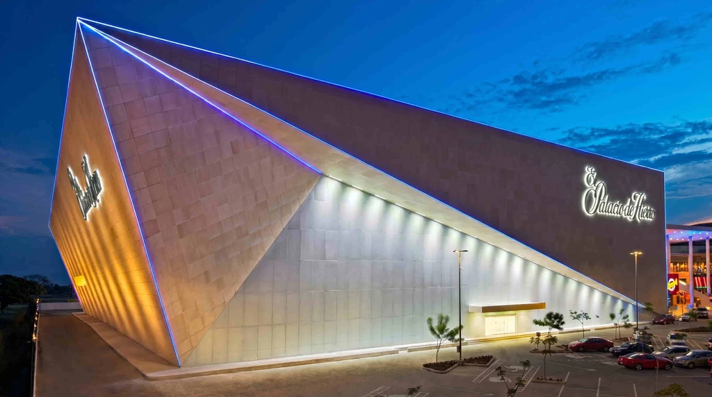
El Palacio de Hierro Villahermosa
- D50 traces the primary angular edges with crisp blue-white accents; LWW-ROWS-W150 washers cover the faceted planes; SP-F620A floodlights uplight the brand signage from 20m+.
- All three fixture types run on one unified DMX512 control system.
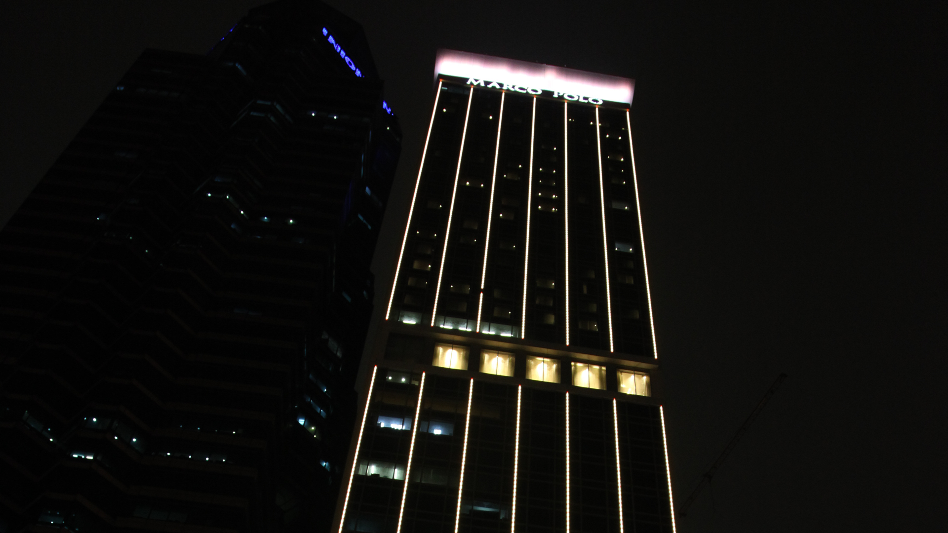
Marco Polo Ortigas Manila
- Hotel tower facade: LLS-OP-D50 outline with LWW-ROWS-W150 in a DMX512 RGBW dynamic wall-washing scheme.
- Continuous vertical lines hold their color consistency across the full tower height.
D50 Design Features That Matter in Project Selection
Each feature below is stated with the project problem it addresses and how the fixture is built.
A note on lifetime ratings Stated so specifiers can see the margin
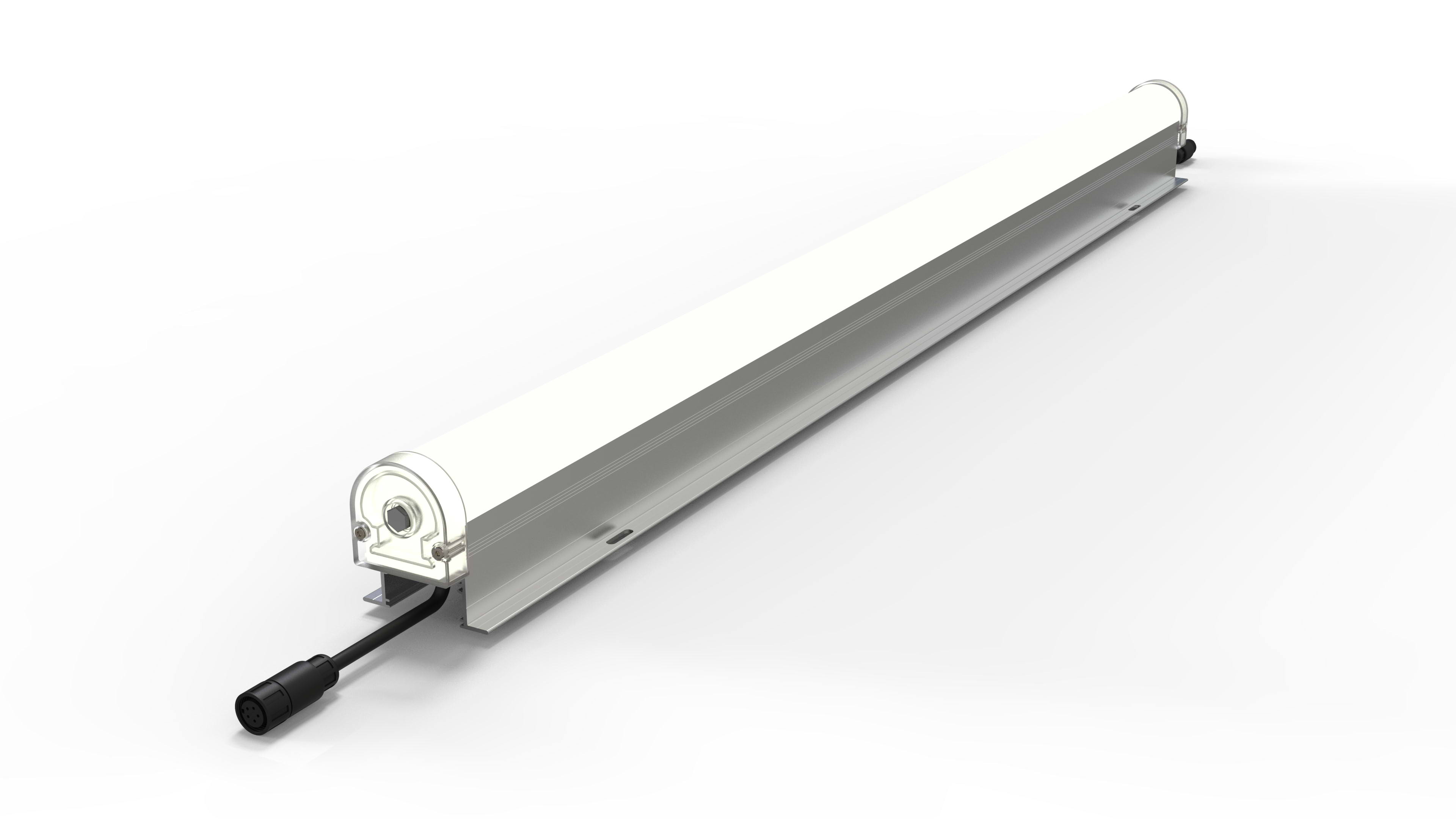
When a diffuser yellows, the whole contour line degrades
Outline luminaires live outdoors for years. When a diffuser yellows, the whole contour line dims and discolors — the design degrades visibly within a few seasons.
How the D50 is built — an anti-UV layer and a diffusing PC layer are co-extruded (“double-extrusion”) into a single diffuser, sealed with a waterproof glass element for the IP66 construction. The co-extruded layer handles uniform light diffusion and UV resistance; the glass element handles structural sealing. The specification commits to at least 3 years of anti-UV / anti-yellowing performance (conditions per the warranty terms — stated separately from the 3-year fixture warranty).
150° Diffusion with Controlled Visible Dots
Direct-view linear luminaires fail visually when individual LED points are visible at close range, or dissolve into a broken dotted line at distance.
150° wide diffusion
A wide diffuse distribution designed for direct-view continuity.
No visible LED points
No individual LED points visible from either frontal or oblique viewing angles.
Photographs, not just numbers
A beam-angle number alone does not prove appearance at every distance. Frontal, oblique, single-fixture and continuous-run photographs with viewing distance and configuration are available on request.
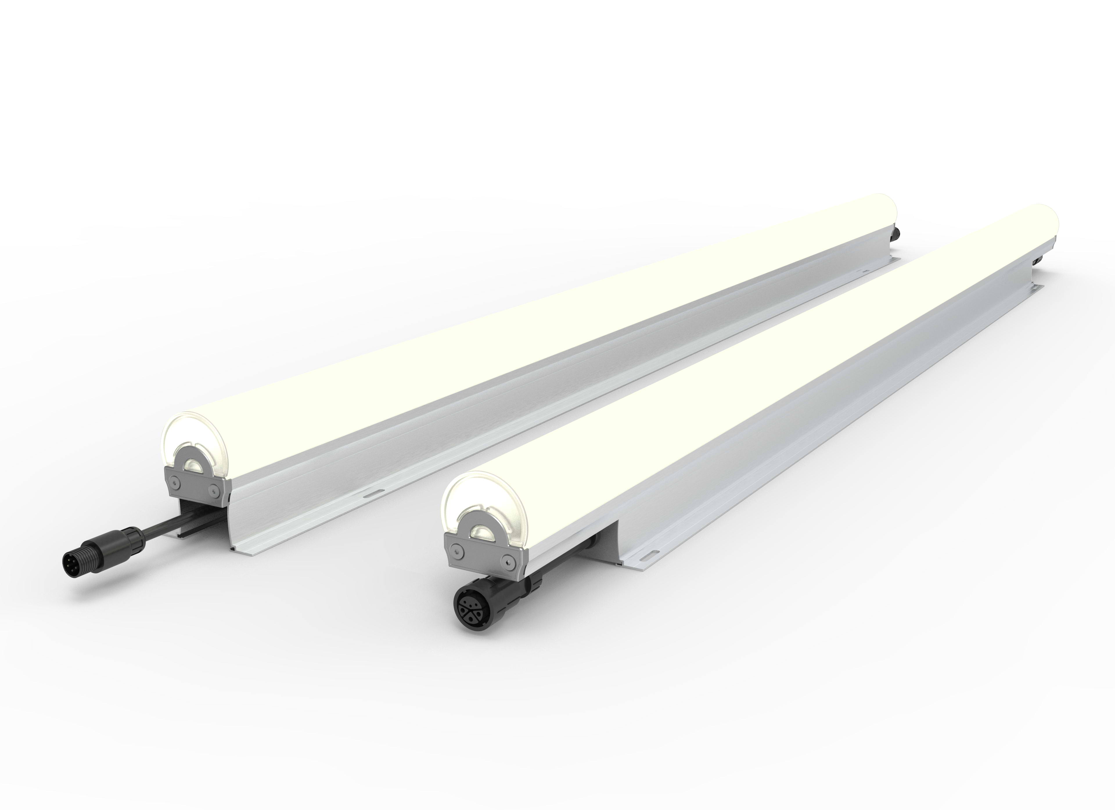
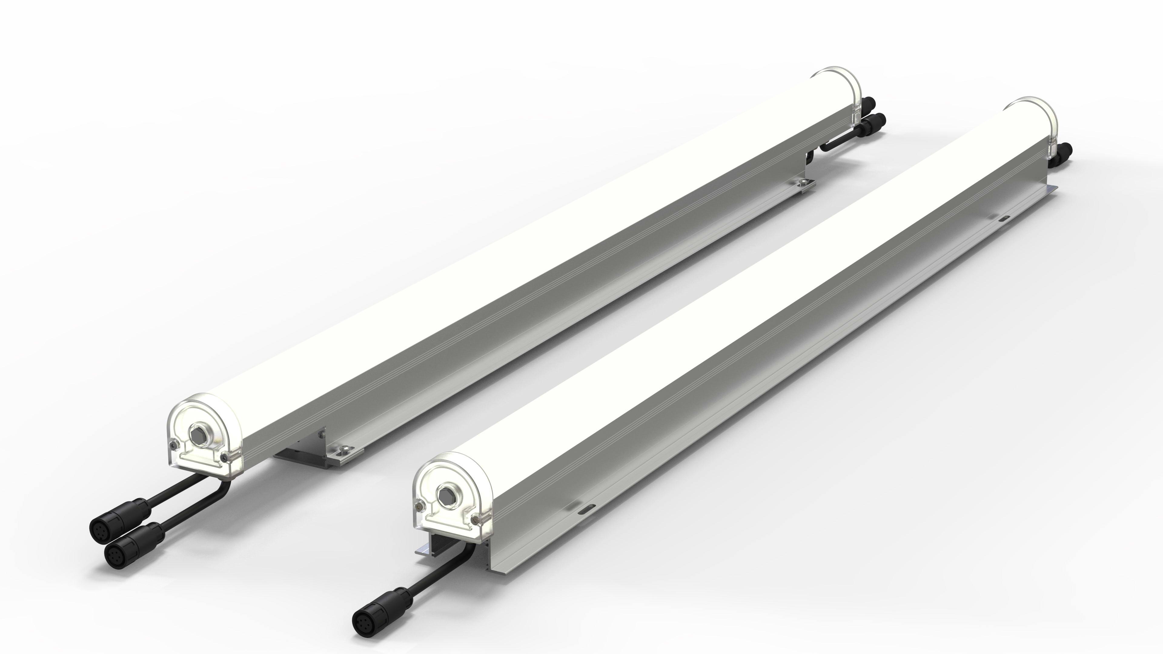
On a continuous contour line, a dark segment at every joint ruins the effect
Continuous outline runs are judged at the joints. Every visible dark gap breaks the line the designer specified.
How the D50 is built — ultra-thin end covers allow fixtures to be joined end to end with minimal visible dark gaps. The specification requires a minimum 5mm fixture-to-fixture spacing to allow disassembly — stated openly so installers plan for it. Installed joints are described as “minimal visible dark gaps,” consistent with joint photography — not an absolute zero-gap promise under all installation conditions.
Two Product Versions: Low-Voltage and Line-Voltage
New projects want to eliminate remote drivers; existing 24V systems want to reuse their power architecture. One fixture cannot do both unless the versions are distinct. The 24V DC and 100–277V AC options are two separate order versions, not one fixture with dual input.
Keeping a 24V architecture
Select the 24V DC version — verify total load, cable runs and voltage drop against the original design.
Dropping remote drivers
New projects or retrofits that can eliminate remote drivers → select the line-voltage version, wired directly to mains.
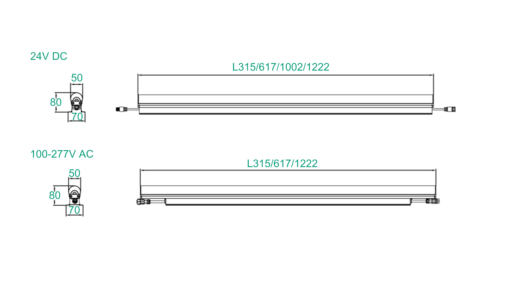
Wiring and control compatibility Per the specification sheet
DMX, RDM and RF — What Each Is Actually For
DMX512
Dynamic dimming and color mixing for architectural outline and media-façade scenes.
RDM
Device management — remote addressing and status functions supported by the fixture.
RF remote
Wireless control for simple installations.
Pixels and channels
The 1222mm version provides 10 independent RGBW pixels (40 DMX channels per 4ft) — the same pixel count as the BCS342 L100 10PX version, allowing channel-mapping comparison. Shorter lengths carry fewer pixels (e.g. the 315mm version divides 18 LEDs into 3 channels), so mapping must be verified per length. A pixel/channel comparison table is available on request.
NoteThe same protocol does not guarantee identical dynamic effects — effects depend on pixel segmentation and scene programming.
Selecting the D50 Length and Configuration
Five lengths solve the module-matching problem. Fix the total run length first, then close the ends with short lengths — no on-site cutting.
Model matrix All five lengths
Lumens stated as white / RGBW per the specification sheet. Power-density variants (21W/m and 24W/m) are documented in the sheet — confirm at order.
1002/1222mm lengths cover long straight runs with fewer fixtures and joints; 315/502/617mm lengths handle terminations, corners and non-standard segments. Fix the total run length first, then close the ends with short lengths — no on-site cutting.
Certification Coverage and Technical Submittal Documents
Low-voltage and line-voltage versions hold separate certification documents. Coverage is stated model by model below — not as a blanket claim.
ETL Authorization to Mark (Intertek)
Report 16090268HKG-001 · Control No. 4009128
UL 2108:2015 Ed.2 + CSA C22.2 No. 250.2:2020. Models listed: LLS-OP-D50-L12, -L6, -L3. L10 and L5 are not shown on this ATM — verify before claiming.
CE Verification of Conformity (Waltek)
Reg. No. WTA24F12313493, Ref. R1L · 2025-04-10
EN IEC 60598-1:2021 · EN 60598-2-4:2018 · EN 62493:2015 · GPSR (EU) 2023/988. All five lengths — 24VDC, Class III, IP66.
CE (Waltek)
Reg. No. WTA25F03061394
IEC 60598-1:2020 · IEC 60598-2-5:2015 · LVD 2014/35/EU. D50 HV coverage is verified per order — request the certificate copy for the selected model.
IP66 — per IEC 60529
EMTEK Test Report EGZ2410080117R00102R (Oct 2024) — conclusion: Pass, LLS-OP-D50 (tested sample).
Custom configurations are assessed case by case and do not automatically inherit standard-model coverage.
Checklist for Replacing Fixtures in an Existing Installation
Verify all nine items before finalizing a replacement plan.
Original model
Full original fixture model and configuration, including order code.
Geometry
Total run length, cross-section, bracket type, hole positions, cable exits.
Power
Original power supply output and total load.
Wiring
Connector pinout and power/signal wiring method.
Control
DMX channel count, addressing and pixel mapping.
Scenes
Whether the original scene files need reprogramming.
Joints
Luminous and color consistency at new/old joints — compare sample fixtures on site.
Samples
On-site sample test records.
Submittals
Submittal documents and approval records.
ReminderSimilar lengths are not guaranteed to share mounting points or brackets — verify all nine items before finalizing a replacement plan. A printable version is available on request.