


Architectural & Bridge Lighting Control Integration. Engineered Downstream Hardware & Commissioning Support.
TPK manufactures the luminaires and engineers the complete downstream control architecture. From universe budgeting and Art-Net/sACN distribution to one-line schematics, factory pre-addressing, opto-isolation, and remote commissioning, we eliminate field integration risks before hardware reaches the site.
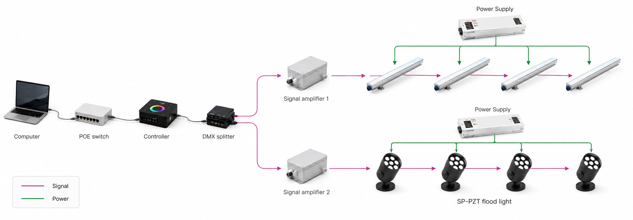
Specified on Pharos, MADRIX, Lumenpulse, or Color Kinetics? Send us your fixture schedule, layout drawings, and control narrative. We review the channel footprints, provide compatible TPK architectural luminaires, and engineer the complete signal, power, and distribution package.
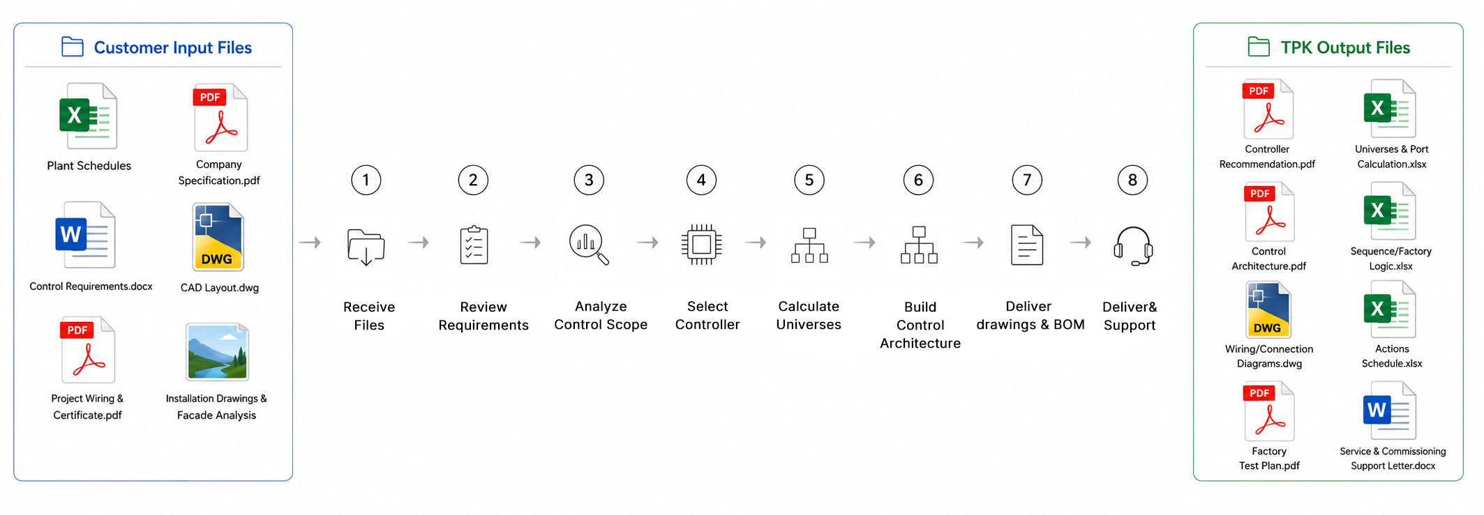
End-to-End Control Engineering: 6 Delivery Stages
Spec & Schedule Audit
Audit fixture schedules, BOQ, CAD layouts, channel footprints, site voltages, and existing controller platforms.
Topology & Network Sizing
Calculate universe budgets (170 RGB / 128 RGBW per port), size Art-Net/sACN nodes, and plan network switch distribution.
Signal & Accessory BOM
Specify opto-isolated splitters (max 32 loads/branch), 120Ω line terminators, mid-run power injection, and branch cabling.
Pre-Addressing & Bench Test
Program DMX start addresses prior to packing, map ports 1:1 to elevations, and run full-system bench loop tests.
As-Built Documentation
Deliver one-line riser schematics, DMX patch schedules, network IP tables, wiring guidelines, and factory test records.
Remote Commissioning
Direct startup assistance: RDM device discovery, network routing checks, show file upload, and field fault tracing.
Submittal & Feasibility Requirements
No redesign required. Submit your existing submittal drawings, fixture schedules, and control specifications—our engineering team audits protocol compatibility, channel loading, and necessary hardware interfaces.
Consultant or Competitor Spec
Evaluate Pharos, MADRIX, Lumenpulse, or Color Kinetics control narratives for 1:1 functional equivalence.
Fixture Schedule & Channel Footprint
Quantities, RGB/RGBW/Pixel channel counts, and universe budgets calculated directly per fixture run.
CAD & Elevation Layouts
Drawings establish central control rack locations, node enclosures, and maximum copper cable run lengths.
Electrical & Certification Scope
Audit site voltage (120–277VAC / 24–48VDC), ETL/cETL compliance, and third-party control handshake protocols.
You send
Fixture schedules, CAD/elevation drawings, channel footprints, operating voltage, and specified control platforms.
TPK reviews
DMX universe budgets, RS-485 distance limits, opto-isolation points, voltage drops, and network topologies.
You receive
One-line riser diagram, controller/gateway sizing, accessory BOM, patch schedule, and factory loop test verification.
System Architecture Sizing Criteria
Universe allocation, port counts, and network hardware are calculated directly from physical cable runs, fixture channel counts, and site distance constraints.
Engineering Criteria
Total channel load, fixture layout, and physical distance dictate gateway ports, universe distribution, and repeaters.
Fixture Quantities
Calculated per facade elevation, bridge pier, or physical control zone.
Channel Footprint
Verified per luminaire: RGB (3-ch), RGBW (4-ch), or custom pixel-mapped profiles.
Total DMX Channels
Calculated per run to ensure fixture runs do not split across universe boundaries.
Universes & Output Ports
Max 512 channels (170 RGB / 128 RGBW) per port with 10–15% spare channel headroom.
Controllers & Node Hardware
Industrial gateways and playback servers selected based on processing load and storage requirements.
What the Control Drawing Shows
- Master controller / playback server location
- Network switch hierarchy & fiber patch bays
- Distributed Art-Net/sACN gateway locations
- DMX output lines & universe channel assignments
- Fixture run order & start address mapping
- Contractor wiring boundaries & power-feed taps
Signal Path Review Criteria
- Max RS-485 copper distance (100m limit)
- Optical isolation (≥2.5kV) & surge suppression
- Industrial Ethernet / single-mode fiber links
- Splitter placement (max 32 loads per physical branch)
- Waterproof disconnect & connector pinouts
- 120Ω bus line termination verification
Hardware Included in the BOM
- Master controllers, nodes, and Art-Net gateways
- Industrial managed Ethernet switches & fiber transceivers
- Opto-isolated DMX/RDM signal splitters
- Controller-side XLR/RJ45 jumper cables
- Mid-run power T-taps & signal branch connectors
- 120Ω molded bus end terminators
Control System Topology Examples
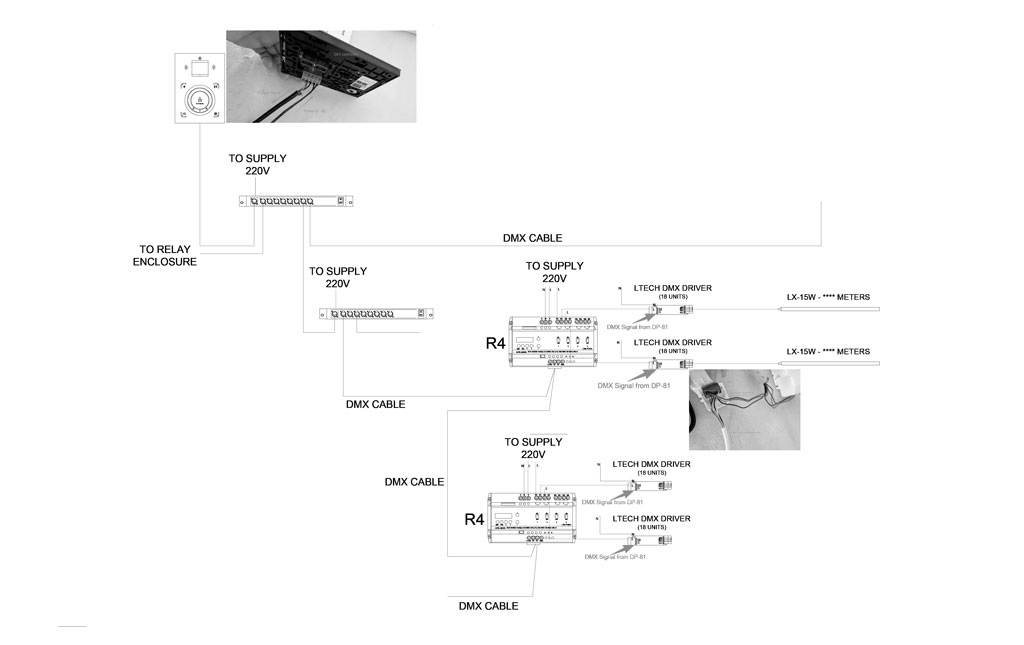
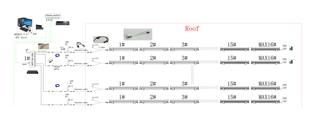
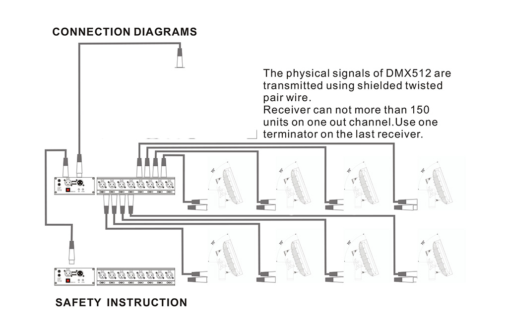
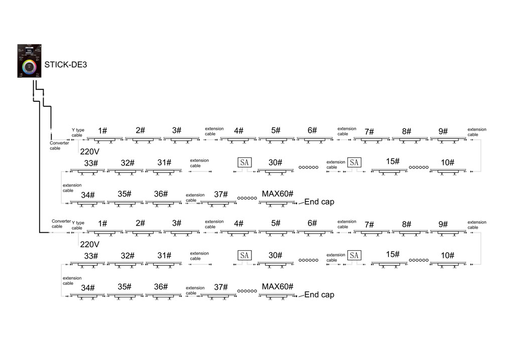
Reference topologies shown. Final controller selection, universe distribution, accessory BOM, and cable routings are engineered to project submittals.
Engineering Principles Behind the Topology
Architecture Before Brand
We analyze channel footprints, standalone playback, user interfaces, and site distances before recommending Pharos, MADRIX, Nicolaudie, or dedicated DMX solutions.
Controller & Gateway Sizing
Outputs, network nodes, and universe capacities include 10–15% spare margin for field adjustments without re-patching.
Strategic Equipment Placement
Gateways and splitters are positioned to minimize RS-485 copper runs, avoid high-voltage conduits, and simplify maintenance.
Project-Specific Schematics
Every engineered package includes a riser diagram showing master controller, IP addressing, nodes, DMX branches, and fixture sequences.
Signal Integrity & Isolation
Bidirectional opto-isolation (≥2.5kV) separates branches to eliminate ground loops and isolate local electrical faults.
Third-Party Integration
Seamlessly map TPK luminaires into existing site infrastructure running Art-Net, sACN, DMX512-A, or RDM.
Complete Hardware Chain: From Server to Luminaire
TPK Standard: Every hardware component listed on the quotation appears on the control riser diagram.
LLT → XLR Adapter
Adapts IP68 molded luminaire leads to standard XLR-3 / XLR-5 control console interfaces.
Y-Type Power Input
Combines mains power and DMX data feed into the first fixture run.
Signal Amplifier
Reconditions weakened DMX waveforms and isolates signal runs exceeding 100m.
5-Core Signal Cable
Heavy-duty outdoor composite cable delivering DMX data and low-voltage power.
Y-Type Mid-Run Power
In-line injection tap for DC voltage re-feed to prevent color shift and voltage drop.
Signal Input Cable
Direct interface lead connecting distribution splitters to the fixture array.
T-Type Mid-Run Power
High-current branch tap for linear fixture daisy chains with distributed power units.
120Ω End Terminator
Absorbs differential signal reflection at the terminal fixture of every RS-485 bus.
Waterproof Connector · 1-to-2
Molded IP68 branch connector for multi-run DMX signal distribution.
Pre-Production Specification Checklist
Luminaire Certification
Verify required regional approvals (ETL/cETL, CE) and supply standard-compliant wiring schematics.
Voltage & Electrical Architecture
Audit 120V/277VAC mains or 24V/48VDC remote driver drops across maximum circuit lengths.
Protocol Standards
Confirm DMX512-A, ANSI E1.20 RDM, Art-Net 4, sACN (E1.31), or DALI-2 interface standards.
Outdoor Environment Ratings
Specify IP67/IP68 cable assemblies, UV-rated jackets, and NEMA 4X / IP66 outdoor enclosures.
Third-Party Compatibility
Validate firmware compatibility and channel profile libraries for third-party control hardware.
Deviation & Discrepancy Log
Identify and resolve discrepancies between architectural specs and proposed hardware before BOM sign-off.
Factory Pre-Configuration & System Validation
We verify full multi-universe control chains on the factory test bench before packaging—eliminating onsite troubleshooting.
01 · Pre-Addressing & Tagging
DMX start channels are pre-programmed via RDM. Fixtures are tagged with physical zone, universe, and channel labels matching CAD drawings.
02 · 1:1 Port & Software Patching
Fixture sequences, universes, and start channels are structured in software to match real-world installation elevations.
03 · Scene Programming & Burn-In
Static scenes, dynamic color chases, and power-cycle behaviors are loaded and loop-tested during factory aging.
04 · Full-Chain System Mock-Up
Representative fixtures, controllers, splitters, and power supplies are connected as a live loop with documented test records.
As-Built Documentation Delivered with Every System
Clean, contractor-ready submittals that allow field installers and electricians to land wires correctly the first time.
Control Riser Schematics
One-line riser diagram showing controller racks, network switches, gateways, splitters, and fixture daisy chains.
Control BOM & Accessory Schedule
Itemized hardware schedule detailing controllers, splitters, power supplies, custom jumpers, and terminators.
DMX Address & Patch Schedule
Spreadsheet mapping fixture tags, physical positions, universe numbers, port assignments, and start channels.
Factory Bench Test Report
Documented verification report and loop playback validation for the assembled control architecture.
Show & Configuration Backups
Software project files, patch maps, network IP tables, and show playback archives stored on USB media.
Installation & Wiring Guidelines
Pinout diagrams, grounding rules, torque specs, and troubleshooting notes for the electrical contractor.
Field Commissioning & Rapid Fault Isolation
Architectural DMX systems must be diagnosed through a structured physical-to-logical sequence. Eliminate guesswork by verifying each layer before replacing hardware on the wall.
4-Layer Diagnostic Protocol
Isolate issues systematically: Power → Signal → Address → Network/Program.
Flickering or Random Strobing
Signal reflection or ground loop. Verify missing 120Ω terminator at end-of-line; ensure shield is grounded at splitter only.
Color Shift or Inverted Channels
Profile mismatch. Audit 8-bit vs. 16-bit fixture mode and verify software patch order (RGBW vs. GRBW) against physical chips.
Duplicate Fixture Response
Overlapping DMX start channels. Recalculate footprint offsets (e.g., RGBW = 4 channels; Fixture 2 must start at ch 5).
Dynamic Chase Runs in Reverse
Physical daisy-chain order inverted from software patch. Invert patch sequence in software rather than rewiring fixtures.
Entire Branch Stays Dark
Check splitter port LED; measure differential DC voltage (D+ to D- should read 1.5–2.5V); bypass first fixture to check RS-485 transceiver.
Controller Cannot Discover Node
IP subnet mismatch (e.g., 2.x.x.x vs 192.168.x.x) or switch blocking Art-Net broadcast. Verify IGMP Snooping and VLAN settings.
Signal Dropouts on Long Runs
Cable capacitance / impedance failure. Replace standard cable with 120Ω shielded twisted-pair; install isolated repeater at 80m.
RDM Discovery Failure
Non-compliant splitters. In-line splitters must support ANSI E1.20 bidirectional communication; replace standard one-way opto-splitters.
Show Stops After Disconnecting PC
Show not written to internal flash memory. Burn file to onboard SD/eMMC and configure RTC or startup trigger to "Loop on Boot".
Field Fixture Replacement
Fast field re-addressing. Use a handheld RDM programmer to write the original DMX start channel before mounting—no show file edit needed.
Third-Party Control Platform Integration
TPK manufactures the luminaires and integrates industry-standard control hardware to match project specifications. Controller brands are supported natively via standard DMX512, RDM, Art-Net, and sACN protocols.
| Platform | Best Fit | Typical TPK Engineering Scope | Official Links |
|---|---|---|---|
| MADRIX | High-density pixel facades, media-driven dynamic video mapping, large-scale Art-Net networks. | MADRIX 5 license sizing, Art-Net gateway configuration, patch schedule generation, and factory bench verification. | |
| Pharos Designer | Permanent architectural lighting, mission-critical infrastructure, distributed DMX/RDM loops. | Pharos LPC / LPC X sizing, RIO G4 topology integration, Designer 2 project setup, and fixture RDM profile validation. | |
| Nicolaudie / Sunlite | Standalone architectural installations, wall-mount touch panels, multi-zone schedule triggers. | STICK-DE3 / DINA-DR1 specification, multi-zone channel planning, standalone scene loading, and factory burn-in. |
MADRIX, Pharos, and Nicolaudie are registered trademarks of their respective owners. Platform integration is engineered for compatibility and does not imply direct brand manufacturing.
Proven Control Deployments in Real Projects
These references represent full control engineering packages—including universe budgeting, signal accessory schedules, factory pre-addressing, and field commissioning.
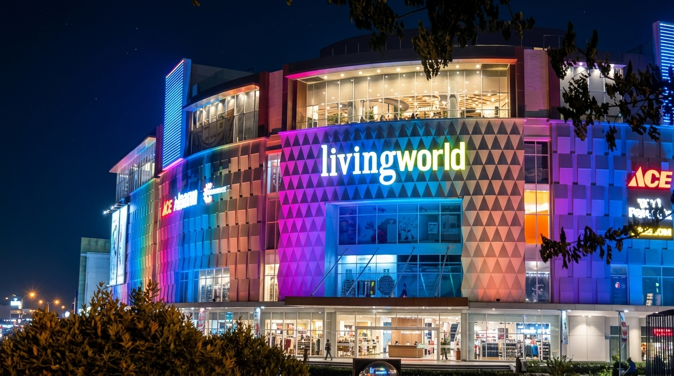
DMX512 | 12 Universes | Nicolaudie STICK-DE3
Architectural facade lighting with DMX-controlled linear luminaires and wall washers. TPK delivered controller sizing, opto-isolated signal distribution, DMX address planning, and pre-commissioned scene files.
View project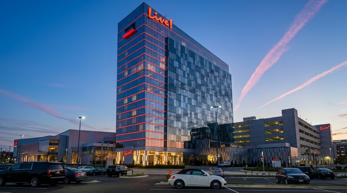
Pharos Control System | DMX Architectural Facade
High-profile facade lighting integrating Pharos controls with ETL-listed architectural luminaires. Engineered as a unified package covering site voltage drops, custom cable assemblies, and remote sign-off.
View project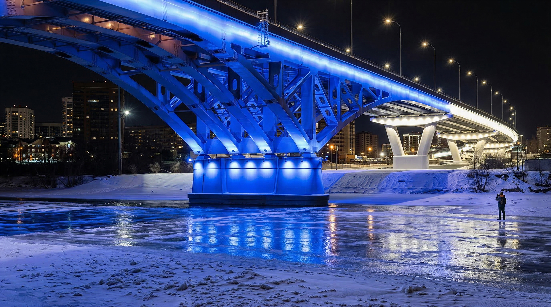
Fiber/eDMX | Pharos LPC | Long Distance Signal
Major infrastructure bridge illumination utilizing single-mode fiber-optic backbones and distributed Art-Net nodes to ensure signal stability across extreme physical spans and harsh outdoor conditions.
View project